Inspiron 27 7000 Service Manual
Page 1
Inspiron 27 7000 Service Manual Computer Model: Inspiron 27-7775 Regulatory Model: W16C Regulatory Type: W16C001
Inspiron 27 7000 Service Manual Computer Model: Inspiron 27-7775 Regulatory Model: W16C Regulatory Type: W16C001

Inspiron 27 7000 Service Manual
Page 5
Removing the power-button board 42 Prerequisites 42 Procedure 42 Replacing the power-button board 44 Procedure 44 Post-requisites 44 Removing the front bezel 45 Prerequisites 45 Procedure 46 Replacing the front bezel 48 Procedure 48 Post-requisites 48 Removing the media-card reader 49 Prerequisites 49 Procedure 49 Replacing the media-card reader 53 Procedure 53 Post-requisites 53 Removing the side I/O-board 55 Prerequisites 55 Procedure 55 Replacing the side I/O-board 57 Procedure 57 Post-requisites 57 5
Removing the power-button board 42 Prerequisites 42 Procedure 42 Replacing the power-button board 44 Procedure 44 Post-requisites 44 Removing the front bezel 45 Prerequisites 45 Procedure 46 Replacing the front bezel 48 Procedure 48 Post-requisites 48 Removing the media-card reader 49 Prerequisites 49 Procedure 49 Replacing the media-card reader 53 Procedure 53 Post-requisites 53 Removing the side I/O-board 55 Prerequisites 55 Procedure 55 Replacing the side I/O-board 57 Procedure 57 Post-requisites 57 5

Inspiron 27 7000 Service Manual
Page 7
Removing the coin-cell battery 70 Prerequisites 70 Procedure 70 Replacing the coin-cell battery 72 Procedure 72 Post-requisites 72 Removing the memory modules 73 Prerequisites 73 Procedure 74 Replacing the memory modules 76 Procedure 76 Post-requisites 77 Removing the solid-state drive 78 Prerequisites 78 Procedure 79 Replacing the solid-state drive 81 Procedure 81 Post-requisites 81 Removing the wireless card 82 Prerequisites 82 Procedure 83 Replacing the wireless card 85 Procedure 85 Post-requisites 86 7
Removing the coin-cell battery 70 Prerequisites 70 Procedure 70 Replacing the coin-cell battery 72 Procedure 72 Post-requisites 72 Removing the memory modules 73 Prerequisites 73 Procedure 74 Replacing the memory modules 76 Procedure 76 Post-requisites 77 Removing the solid-state drive 78 Prerequisites 78 Procedure 79 Replacing the solid-state drive 81 Procedure 81 Post-requisites 81 Removing the wireless card 82 Prerequisites 82 Procedure 83 Replacing the wireless card 85 Procedure 85 Post-requisites 86 7

Inspiron 27 7000 Service Manual
Page 9
Removing the system board 105 Prerequisites 105 Procedure 106 Replacing the system board 109 Procedure 109 Post-requisites 110 Removing the middle frame 111 Prerequisites 111 Procedure 112 Replacing the middle frame 113 Procedure 113 Post-requisites 116 Removing the display panel 118 Prerequisites 118 Procedure 118 Replacing the display panel 122 Procedure 122 Post-requisites 126 Flashing the BIOS 127 BIOS setup program 128 BIOS overview 128 Entering BIOS setup program 128 System setup options 129 Clearing forgotten passwords 134 Prerequisites 134 9
Removing the system board 105 Prerequisites 105 Procedure 106 Replacing the system board 109 Procedure 109 Post-requisites 110 Removing the middle frame 111 Prerequisites 111 Procedure 112 Replacing the middle frame 113 Procedure 113 Post-requisites 116 Removing the display panel 118 Prerequisites 118 Procedure 118 Replacing the display panel 122 Procedure 122 Post-requisites 126 Flashing the BIOS 127 BIOS setup program 128 BIOS overview 128 Entering BIOS setup program 128 System setup options 129 Clearing forgotten passwords 134 Prerequisites 134 9

Inspiron 27 7000 Service Manual
Page 11
... of your operating system for shut-down instructions. 3 Disconnect your computer and all attached devices from their electrical outlets. 4 Disconnect all open files and exit all attached network devices and peripherals, such as keyboard, mouse, and monitor from your computer. 5 Remove any media card and optical disc from your computer depending on the configuration you ordered. Click Start → Power → Shut down . 11 Identifier GUID-5D3B1051-9384...
... of your operating system for shut-down instructions. 3 Disconnect your computer and all attached devices from their electrical outlets. 4 Disconnect all open files and exit all attached network devices and peripherals, such as keyboard, mouse, and monitor from your computer. 5 Remove any media card and optical disc from your computer depending on the configuration you ordered. Click Start → Power → Shut down . 11 Identifier GUID-5D3B1051-9384...
Inspiron 27 7000 Service Manual
Page 12
... troubleshooting and repairs as the metal at www.dell.com/ regulatory_compliance. While you finish working inside your computer, ground yourself by touching an unpainted metal surface, such as authorized or directed by their edges, and avoid touching pins and contacts. CAUTION: Before touching anything inside your computer. CAUTION: When you must disengage before opening the computer cover or panels. When connecting cables...
... troubleshooting and repairs as the metal at www.dell.com/ regulatory_compliance. While you finish working inside your computer, ground yourself by touching an unpainted metal surface, such as authorized or directed by their edges, and avoid touching pins and contacts. CAUTION: Before touching anything inside your computer. CAUTION: When you must disengage before opening the computer cover or panels. When connecting cables...

Inspiron 27 7000 Service Manual
Page 16
Identifier GUID-06588814-2678-4667-9FF9-C009F4BCE185 Status Released After working inside your computer CAUTION: Leaving stray or loose screws inside your computer may severely damage your computer. 1 Replace all screws and ensure that no stray screws remain inside your computer. 2 Connect any external devices, peripherals, or cables you removed before working on your computer. 3 Replace any media cards, discs, or any other parts that you removed before working on your computer. 4 Connect your computer and all attached devices to their electrical outlets. 5 Turn on your computer. 16
Identifier GUID-06588814-2678-4667-9FF9-C009F4BCE185 Status Released After working inside your computer CAUTION: Leaving stray or loose screws inside your computer may severely damage your computer. 1 Replace all screws and ensure that no stray screws remain inside your computer. 2 Connect any external devices, peripherals, or cables you removed before working on your computer. 3 Replace any media cards, discs, or any other parts that you removed before working on your computer. 4 Connect your computer and all attached devices to their electrical outlets. 5 Turn on your computer. 16

Inspiron 27 7000 Service Manual
Page 27
... and follow the instructions in After working inside your computer. After working inside your computer, follow the steps in sleep or on state. For more safety best practices, see the Regulatory Compliance home page at www.dell.com/ regulatory_compliance. Exercise care when handling the hard drive. Identifier GUID-5DE1E07B-4633-4536-ACBF-4A3067007FE0 Status Released Removing the hard drive WARNING: Before working inside your computer...
... and follow the instructions in After working inside your computer. After working inside your computer, follow the steps in sleep or on state. For more safety best practices, see the Regulatory Compliance home page at www.dell.com/ regulatory_compliance. Exercise care when handling the hard drive. Identifier GUID-5DE1E07B-4633-4536-ACBF-4A3067007FE0 Status Released Removing the hard drive WARNING: Before working inside your computer...

Inspiron 27 7000 Service Manual
Page 30
... back cover. 30 CAUTION: Hard drives are fragile. Identifier GUID-8D72BB77-0F8B-428E-A98E-FF7DA2CDA899 Status Released Replacing the hard drive WARNING: Before working inside your computer, read the safety information that shipped with the screw holes on the hard drive. 2 Replace the three screws (M3x3.5) that secure the hard drive to the hard-drive bracket. 3 Connect the power and data cable to the hard drive. 4 Slide the hard-drive assembly into the hard-drive...
... back cover. 30 CAUTION: Hard drives are fragile. Identifier GUID-8D72BB77-0F8B-428E-A98E-FF7DA2CDA899 Status Released Replacing the hard drive WARNING: Before working inside your computer, read the safety information that shipped with the screw holes on the hard drive. 2 Replace the three screws (M3x3.5) that secure the hard drive to the hard-drive bracket. 3 Connect the power and data cable to the hard drive. 4 Slide the hard-drive assembly into the hard-drive...

Inspiron 27 7000 Service Manual
Page 105
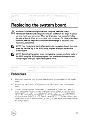
... make the appropriate changes again after you replace the system board. You must enter the Service Tag in After working inside your computer. Identifier GUID-FBBF0EEB-05FB-46DE-8B76-119C4EF76D05 Status Released Prerequisites 1 Remove the back cover. 2 Remove the system-board shield. 3 Remove the memory modules. 4 Remove the solid-state drive. 5 Remove the wireless card. 6 Remove the heat sink. 7 Remove the processor. 105 NOTE: Replacing the system board removes any changes you have made to the BIOS using the BIOS setup...
... make the appropriate changes again after you replace the system board. You must enter the Service Tag in After working inside your computer. Identifier GUID-FBBF0EEB-05FB-46DE-8B76-119C4EF76D05 Status Released Prerequisites 1 Remove the back cover. 2 Remove the system-board shield. 3 Remove the memory modules. 4 Remove the solid-state drive. 5 Remove the wireless card. 6 Remove the heat sink. 7 Remove the processor. 105 NOTE: Replacing the system board removes any changes you have made to the BIOS using the BIOS setup...
Inspiron 27 7000 Service Manual
Page 109
.... 3 Connect the microphone cable (DMIC1), camera cable (WEBCAM), side I/Oboard cable (MB-SUSBC), media-card reader cable (SDRDC1), speaker cable (SPEAKER), subwoofer cable (WOOFC1), I/O-board power cable (RPWRC1), I/O-board cable (LAUOC1), USB Type-C cable (MB-TYPEC1), hard-drive power cable (SATA_PWR1), and I/O cable (RUSBC1) to the BIOS using the BIOS setup program. You must enter the Service Tag in the BIOS setup program after you have made to their respective connectors on the system board. 109 NOTE: Replacing the system board removes any changes you replace the system board.
.... 3 Connect the microphone cable (DMIC1), camera cable (WEBCAM), side I/Oboard cable (MB-SUSBC), media-card reader cable (SDRDC1), speaker cable (SPEAKER), subwoofer cable (WOOFC1), I/O-board power cable (RPWRC1), I/O-board cable (LAUOC1), USB Type-C cable (MB-TYPEC1), hard-drive power cable (SATA_PWR1), and I/O cable (RUSBC1) to the BIOS using the BIOS setup program. You must enter the Service Tag in the BIOS setup program after you have made to their respective connectors on the system board. 109 NOTE: Replacing the system board removes any changes you replace the system board.

Inspiron 27 7000 Service Manual
Page 128
... expert computer user, do not change a user-selectable option, such as the user password, type of hard drive installed, and enabling or disabling base devices. Identifier GUID-1432A924-49E9-4080-961D-2AFBDAF42039 Status Released Entering BIOS setup program 1 Turn on (or restart) your computer, such as the amount of RAM and the size of the hard drive. • Change the system configuration information. • Set or change the settings in your computer. 128 Identifier GUID-7C4079DF-9FF4...
... expert computer user, do not change a user-selectable option, such as the user password, type of hard drive installed, and enabling or disabling base devices. Identifier GUID-1432A924-49E9-4080-961D-2AFBDAF42039 Status Released Entering BIOS setup program 1 Turn on (or restart) your computer, such as the amount of RAM and the size of the hard drive. • Change the system configuration information. • Set or change the settings in your computer. 128 Identifier GUID-7C4079DF-9FF4...

Inspiron 27 7000 Service Manual
Page 130
... the SATA 2 connector. Default: Enabled. Default: AHCI. Default: Enabled. Virtualization Specify whether a Virtual Machine Monitor (VMM) can utilize the additional hardware capabilities provided by Intel Virtualization Technology. Default: Enabled. Miscellaneous Devices Advanced-Miscellaneous Devices BIOS Recovery from Hard Drive Enable you to recover from certain corrupted BIOS conditions from certain corrupted BIOS conditions. Memory Speed Displays the memory speed in MHz. BIOS AutoRecovery Enable or disable BIOS auto-recovery from a recovery file on -board LAN controller...
... the SATA 2 connector. Default: Enabled. Default: AHCI. Default: Enabled. Virtualization Specify whether a Virtual Machine Monitor (VMM) can utilize the additional hardware capabilities provided by Intel Virtualization Technology. Default: Enabled. Miscellaneous Devices Advanced-Miscellaneous Devices BIOS Recovery from Hard Drive Enable you to recover from certain corrupted BIOS conditions from certain corrupted BIOS conditions. Memory Speed Displays the memory speed in MHz. BIOS AutoRecovery Enable or disable BIOS auto-recovery from a recovery file on -board LAN controller...

Inspiron 27 7000 Service Manual
Page 131
... using a network message. Default: Disabled. Advanced-Miscellaneous Devices Always Perform Integrity Check Enable or disable the integrity check function. Default: Disabled. USB Configuration Advanced-USB Configuration Rear USB Ports Side USB Ports USB debug Enable or disable the USB ports at the side of your computer. Enable or disable the USB ports at the back of your computer. NOTE: This option can be enabled only if the Deep Sleep Mode is restored. AC Recovery Select the action the computer takes when power is set to wake...
... using a network message. Default: Disabled. Advanced-Miscellaneous Devices Always Perform Integrity Check Enable or disable the integrity check function. Default: Disabled. USB Configuration Advanced-USB Configuration Rear USB Ports Side USB Ports USB debug Enable or disable the USB ports at the side of your computer. Enable or disable the USB ports at the back of your computer. NOTE: This option can be enabled only if the Deep Sleep Mode is restored. AC Recovery Select the action the computer takes when power is set to wake...

Inspiron 27 7000 Service Manual
Page 138
...indicates that the power supply or another device in hibernation or turned off indicating the Recovery image is unable to boot to the operating system. This 2,3 pattern continues until the computer is turned off . System diagnostic lights Light pattern Problem description 1 System board, BIOS corruption, or ROM error 3 System board, Chipset error, Clock failure, Gate A20 failure, Super I/O failure, or Keyboard controller failure 4 Memory or RAM failure 5 Coin-cell battery failure 6 GPU failure 7 CPU failure 8 Display failure 3,6 BIOS recovery image not found . The...
...indicates that the power supply or another device in hibernation or turned off indicating the Recovery image is unable to boot to the operating system. This 2,3 pattern continues until the computer is turned off . System diagnostic lights Light pattern Problem description 1 System board, BIOS corruption, or ROM error 3 System board, Chipset error, Clock failure, Gate A20 failure, Super I/O failure, or Keyboard controller failure 4 Memory or RAM failure 5 Coin-cell battery failure 6 GPU failure 7 CPU failure 8 Display failure 3,6 BIOS recovery image not found . The...

Inspiron 27 7000 Service Manual
Page 139
Camera status light: Indicates whether the camera is in use. 139 Camera is in use . • Solid white - Light pattern 3,7 Problem description BIOS recovery image found but invalid The computer may emit a series of beeps during start-up if the errors or problems cannot be displayed. The repetitive beep codes help the user troubleshoot problems with the computer. Camera is not in use . • Off -
Camera status light: Indicates whether the camera is in use. 139 Camera is in use . • Solid white - Light pattern 3,7 Problem description BIOS recovery image found but invalid The computer may emit a series of beeps during start-up if the errors or problems cannot be displayed. The repetitive beep codes help the user troubleshoot problems with the computer. Camera is not in use . • Off -

Inspiron 27 7000 Setup and Specifications
Page 10
PowerShare enables you to charge your USB devices even when your devices using the PowerShare port. You must connect the power adapter to charge your computer is turned off or in hibernate state, you must enable this feature in the BIOS setup program. 10 Provides data transfer speeds up to the SD card. 2 USB 3.1 Generation 1 port with Windows Hello face authentication. Enables you to video chat, capture photos, and record videos. 4 Infrared...
PowerShare enables you to charge your USB devices even when your devices using the PowerShare port. You must connect the power adapter to charge your computer is turned off or in hibernate state, you must enable this feature in the BIOS setup program. 10 Provides data transfer speeds up to the SD card. 2 USB 3.1 Generation 1 port with Windows Hello face authentication. Enables you to video chat, capture photos, and record videos. 4 Infrared...

Inspiron 27 7000 Setup and Specifications
Page 11
... network or internet access. Bottom 1 Service Tag label The Service Tag is a unique alphanumeric identifier that enables Dell service technicians to identify the hardware components in your computer and access warranty information. 2 Power-adapter port Connect a power adapter to provide power to your computer. 3 Network port (with lights) Connect an Ethernet (RJ45) cable from a router or a broadband modem for 4 seconds to turn on . NOTE: Certain USB devices may not charge when the computer is turned off , in sleep...
... network or internet access. Bottom 1 Service Tag label The Service Tag is a unique alphanumeric identifier that enables Dell service technicians to identify the hardware components in your computer and access warranty information. 2 Power-adapter port Connect a power adapter to provide power to your computer. 3 Network port (with lights) Connect an Ethernet (RJ45) cable from a router or a broadband modem for 4 seconds to turn on . NOTE: Certain USB devices may not charge when the computer is turned off , in sleep...

Inspiron 27 7000 Setup and Specifications
Page 13
.... Back panel 1 HDMI-in hibernate state, you to charge your computer. 4 USB 3.1 Generation 1 port with PowerShare Connect peripherals such as storage devices and printers. Provides data transfer speeds up to charge the device. 5 USB 2.0 port Connect peripherals such as storage devices and printers. In such cases, turn on the computer to 5 Gbps. Provides data transfer speeds up to 5 Gbps. 3 Security-cable slot (for Kensington locks) Connect a security cable to...
.... Back panel 1 HDMI-in hibernate state, you to charge your computer. 4 USB 3.1 Generation 1 port with PowerShare Connect peripherals such as storage devices and printers. Provides data transfer speeds up to charge the device. 5 USB 2.0 port Connect peripherals such as storage devices and printers. In such cases, turn on the computer to 5 Gbps. Provides data transfer speeds up to 5 Gbps. 3 Security-cable slot (for Kensington locks) Connect a security cable to...

Inspiron 27 7000 Setup and Specifications
Page 17
... SSD card Communications Table 7. Speed Configurations supported 2400 MHz 8 GB, 12 GB, 16 GB, 24 GB, and 32 GB Ports and connectors Table 5. Communication specifications Ethernet Wireless 10/100/1000 Mbps Ethernet controller integrated on system board • Wi-Fi 802.11a/b/g/n/ac • Bluetooth 4.1 17 Ports and connectors specifications External: Network One RJ45 port USB • One USB 3.1 Generation 1 Type C port • Two USB 3.1 Generation 1 ports • Two USB 3.1 Generation 1 ports with PowerShare • Two USB 2.0 ports Audio/Video...
... SSD card Communications Table 7. Speed Configurations supported 2400 MHz 8 GB, 12 GB, 16 GB, 24 GB, and 32 GB Ports and connectors Table 5. Communication specifications Ethernet Wireless 10/100/1000 Mbps Ethernet controller integrated on system board • Wi-Fi 802.11a/b/g/n/ac • Bluetooth 4.1 17 Ports and connectors specifications External: Network One RJ45 port USB • One USB 3.1 Generation 1 Type C port • Two USB 3.1 Generation 1 ports • Two USB 3.1 Generation 1 ports with PowerShare • Two USB 2.0 ports Audio/Video...


