Service Manual
Page 1
....; Microsoft, Windows, and Windows Vista are trademarks of your computer. Information in this text: Dell, the DELL logo, Inspiron, and Vostro are either potential damage to hardware or loss of Dell Inc. CAUTION: A CAUTION indicates potential for I/O Connectors Notes, Notices, and Cautions NOTE: ...document to refer to either the entities claiming the marks and names or their products. Dell Inc. A00 Dell™ Vostro™ 1700 and Inspiron™ 1720/1721 Service Manual Before You Begin ExpressCards Using the Memory Card Reader Optical Drive Hard Drive Hinge Cover ...
....; Microsoft, Windows, and Windows Vista are trademarks of your computer. Information in this text: Dell, the DELL logo, Inspiron, and Vostro are either potential damage to hardware or loss of Dell Inc. CAUTION: A CAUTION indicates potential for I/O Connectors Notes, Notices, and Cautions NOTE: ...document to refer to either the entities claiming the marks and names or their products. Dell Inc. A00 Dell™ Vostro™ 1700 and Inspiron™ 1720/1721 Service Manual Before You Begin ExpressCards Using the Memory Card Reader Optical Drive Hard Drive Hinge Cover ...
Service Manual
Page 2
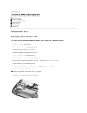
... the Optical Drive). 3. Remove the M2.5 x 5-mm screw that secures the wireless sniffer board to Contents Page Computer Base and Components Dell™ Vostro™ 1700 and Inspiron™ 1720/1721 Service Manual Wireless Sniffer Board Audio Connector Board Consumer Infrared (CIR) Board USB Connector Board Modem Connector ExpressCard Cage Computer Base Wireless Sniffer Board...
... the Optical Drive). 3. Remove the M2.5 x 5-mm screw that secures the wireless sniffer board to Contents Page Computer Base and Components Dell™ Vostro™ 1700 and Inspiron™ 1720/1721 Service Manual Wireless Sniffer Board Audio Connector Board Consumer Infrared (CIR) Board USB Connector Board Modem Connector ExpressCard Cage Computer Base Wireless Sniffer Board...
Service Manual
Page 10
... authorized by your warranty. Disconnect any telephone or network cables from their electrical outlets. Back to Contents Page Before You Begin Dell™ Vostro™ 1700 and Inspiron™ 1720/1721 Service Manual Recommended Tools Before Working Inside Your Computer This document provides procedures for removing and installing the components in this document may appear...
... authorized by your warranty. Disconnect any telephone or network cables from their electrical outlets. Back to Contents Page Before You Begin Dell™ Vostro™ 1700 and Inspiron™ 1720/1721 Service Manual Recommended Tools Before Working Inside Your Computer This document provides procedures for removing and installing the components in this document may appear...
Service Manual
Page 12
...power. Locate the latest BIOS update file for one time only. The Save In window appears. 7. The file downloads to your computer at support.dell.com. 4. The file icon appears on the screen. Press , select Save/Exit, and press to view the Save In menu, select Desktop,...: Do not interrupt this Agreement. Click Close if the Download Complete window appears. Back to Contents Page Flashing the BIOS Dell™ Vostro™ 1700 and Inspiron™ 1720/1721 Service Manual Flashing the BIOS From a CD Flashing the BIOS From the Hard Drive If a BIOS-update program CD is provided with...
...power. Locate the latest BIOS update file for one time only. The Save In window appears. 7. The file downloads to your computer at support.dell.com. 4. The file icon appears on the screen. Press , select Save/Exit, and press to view the Save In menu, select Desktop,...: Do not interrupt this Agreement. Click Close if the Download Complete window appears. Back to Contents Page Flashing the BIOS Dell™ Vostro™ 1700 and Inspiron™ 1720/1721 Service Manual Flashing the BIOS From a CD Flashing the BIOS From the Hard Drive If a BIOS-update program CD is provided with...
Service Manual
Page 14
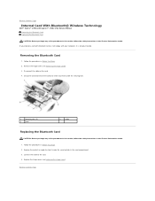
... Before You Begin. 2. Follow the procedures in Before You Begin. 2. Back to Contents Page Internal Card With Bluetooth® Wireless Technology Dell™ Vostro™ 1700 and Inspiron™ 1720/1721 Service Manual Removing the Bluetooth Card Replacing the Bluetooth Card CAUTION: Before you begin any of the procedures in this section, follow the safety...
... Before You Begin. 2. Follow the procedures in Before You Begin. 2. Back to Contents Page Internal Card With Bluetooth® Wireless Technology Dell™ Vostro™ 1700 and Inspiron™ 1720/1721 Service Manual Removing the Bluetooth Card Replacing the Bluetooth Card CAUTION: Before you begin any of the procedures in this section, follow the safety...
Service Manual
Page 15
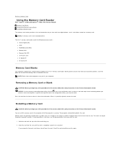
Back to Contents Page Using the Memory Card Reader Dell™ Vostro™ 1700 and Inspiron™ 1720/1721 Service Manual Memory Card Blanks Removing a Memory Card or Blank Installing a Memory Card The memory card reader provides a fast and convenient way to prevent incorrect insertion. Blanks ...
Back to Contents Page Using the Memory Card Reader Dell™ Vostro™ 1700 and Inspiron™ 1720/1721 Service Manual Memory Card Blanks Removing a Memory Card or Blank Installing a Memory Card The memory card reader provides a fast and convenient way to prevent incorrect insertion. Blanks ...
Service Manual
Page 17
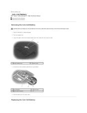
... aside. 1 memory module cover 2 captive screw 4. Follow the procedures in the Product Information Guide. 1. Back to Contents Page Coin-Cell Battery Dell™ Vostro™ 1700 and Inspiron™ 1720/1721 Service Manual Removing the Coin-Cell Battery Replacing the Coin-Cell Battery Removing the Coin-Cell Battery CAUTION: Before you begin any of the...
... aside. 1 memory module cover 2 captive screw 4. Follow the procedures in the Product Information Guide. 1. Back to Contents Page Coin-Cell Battery Dell™ Vostro™ 1700 and Inspiron™ 1720/1721 Service Manual Removing the Coin-Cell Battery Replacing the Coin-Cell Battery Removing the Coin-Cell Battery CAUTION: Before you begin any of the...
Service Manual
Page 19
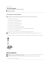
... transfer areas on the processor module. 11. Lift the processor module from the ZIF socket. Back to Contents Page Processor Module Dell™ Vostro™ 1700 and Inspiron™ 1720/1721 Service Manual Removing the Processor Module Replacing the Processor Module Removing the Processor Module CAUTION: Before you begin the following procedure, follow the safety...
... transfer areas on the processor module. 11. Lift the processor module from the ZIF socket. Back to Contents Page Processor Module Dell™ Vostro™ 1700 and Inspiron™ 1720/1721 Service Manual Removing the Processor Module Replacing the Processor Module Removing the Processor Module CAUTION: Before you begin the following procedure, follow the safety...
Service Manual
Page 22
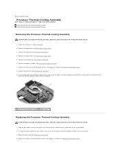
... begin the following procedure, follow the safety instructions in the Product Information Guide. 1. Back to Contents Page Processor Thermal-Cooling Assembly Dell™ Vostro™ 1700 and Inspiron™ 1720/1721 Service Manual Removing the Processor Thermal-Cooling Assembly Replacing the Processor Thermal-Cooling Assembly Removing the Processor Thermal-Cooling Assembly CAUTION: Before you begin...
... begin the following procedure, follow the safety instructions in the Product Information Guide. 1. Back to Contents Page Processor Thermal-Cooling Assembly Dell™ Vostro™ 1700 and Inspiron™ 1720/1721 Service Manual Removing the Processor Thermal-Cooling Assembly Replacing the Processor Thermal-Cooling Assembly Removing the Processor Thermal-Cooling Assembly CAUTION: Before you begin...
Service Manual
Page 24
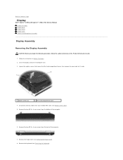
....5 x 8-mm screws from the back of the computer. 6. Remove the hinge cover (see Removing the Keyboard). Back to Contents Page Display Dell™ Vostro™ 1700 and Inspiron™ 1720/1721 Service Manual Display Assembly Display Bezel Display Panel Display Latch Camera and Microphone Assembly Display Assembly Removing the Display Assembly CAUTION: Before you begin...
....5 x 8-mm screws from the back of the computer. 6. Remove the hinge cover (see Removing the Keyboard). Back to Contents Page Display Dell™ Vostro™ 1700 and Inspiron™ 1720/1721 Service Manual Display Assembly Display Bezel Display Panel Display Latch Camera and Microphone Assembly Display Assembly Removing the Display Assembly CAUTION: Before you begin...
Service Manual
Page 32
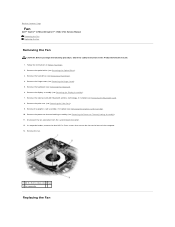
... system board connector. 12. In sequential order, remove the four M2.5 x 5-mm screws that secure the fan to Contents Page Fan Dell™ Vostro™ 1700 and Inspiron™ 1720/1721 Service Manual Removing the Fan Replacing the Fan Removing the Fan CAUTION: Before you begin the following procedure, follow the safety instructions in Before...
... system board connector. 12. In sequential order, remove the four M2.5 x 5-mm screws that secure the fan to Contents Page Fan Dell™ Vostro™ 1700 and Inspiron™ 1720/1721 Service Manual Removing the Fan Replacing the Fan Removing the Fan CAUTION: Before you begin the following procedure, follow the safety instructions in Before...
Service Manual
Page 34
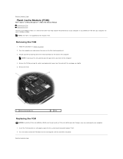
... FCM NOTICE: Install the FCM in Before You Begin. 2. Back to the computer. 4. Back to Contents Page Flash Cache Module (FCM) Dell™ Vostro™ 1700 and Inspiron™ 1720/1721 Service Manual Removing the FCM Replacing the FCM The Flash Cache Module (FCM) is an internal flash drive that helps improve the performance of...
... FCM NOTICE: Install the FCM in Before You Begin. 2. Back to the computer. 4. Back to Contents Page Flash Cache Module (FCM) Dell™ Vostro™ 1700 and Inspiron™ 1720/1721 Service Manual Removing the FCM Replacing the FCM The Flash Cache Module (FCM) is an internal flash drive that helps improve the performance of...
Service Manual
Page 35
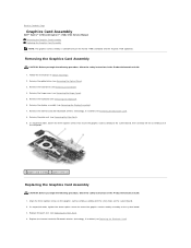
...tighten the three captive screws to secure the graphics card assembly assembly to Contents Page Graphics Card Assembly Dell™ Vostro™ 1700 and Inspiron™ 1720/1721 Service Manual Removing the Graphics Card Assembly Replacing the Graphics Card Assembly NOTE: The graphics card assembly is available ...in the Product Information Guide. 1. Remove the internal card with the screw holes on the Vostro 1700 (standard) and the Inspiron 1720 (optional). In sequential order, loosen the three captive screws that secure the graphics card assembly to the system board, then carefully...
...tighten the three captive screws to secure the graphics card assembly assembly to Contents Page Graphics Card Assembly Dell™ Vostro™ 1700 and Inspiron™ 1720/1721 Service Manual Removing the Graphics Card Assembly Replacing the Graphics Card Assembly NOTE: The graphics card assembly is available ...in the Product Information Guide. 1. Remove the internal card with the screw holes on the Vostro 1700 (standard) and the Inspiron 1720 (optional). In sequential order, loosen the three captive screws that secure the graphics card assembly to the system board, then carefully...
Service Manual
Page 37
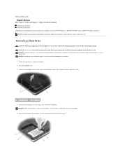
... drive cover, then remove the cover and set it aside. 1 captive screws (2) 2 hard drive cover 4. Back to Contents Page Hard Drive Dell™ Vostro™ 1700 and Inspiron™ 1720/1721 Service Manual Removing a Hard Drive Replacing a Hard Drive Depending on the configuration you begin any of the procedures in this section, follow the safety...
... drive cover, then remove the cover and set it aside. 1 captive screws (2) 2 hard drive cover 4. Back to Contents Page Hard Drive Dell™ Vostro™ 1700 and Inspiron™ 1720/1721 Service Manual Removing a Hard Drive Replacing a Hard Drive Depending on the configuration you begin any of the procedures in this section, follow the safety...
Service Manual
Page 39
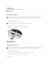
Back to Contents Page Hinge Cover Dell™ Vostro™ 1700 and Inspiron™ 1720/1721 Service Manual Removing the Hinge Cover Replacing the Hinge Cover Removing the Hinge Cover CAUTION: Before you begin any of the procedures in this section, follow the ...
Back to Contents Page Hinge Cover Dell™ Vostro™ 1700 and Inspiron™ 1720/1721 Service Manual Removing the Hinge Cover Replacing the Hinge Cover Removing the Hinge Cover CAUTION: Before you begin any of the procedures in this section, follow the ...
Service Manual
Page 40
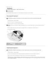
... the Keyboard CAUTION: Before you begin any of the procedures in this section, follow the safety instructions in your Owner's Manual. Slide the keyboard toward the back of the keyboard. Applying even pressure to keep the keyboard flat, slide the keyboard ...hinge cover (see "Using the Keyboard and Touchpad" in the Product Information Guide. 1. Back to Contents Page Keyboard Dell™ Vostro™ 1700 and Inspiron™ 1720/1721 Service Manual Removing the Keyboard Replacing the Keyboard For more information about the keyboard, see Removing the Hinge Cover). 3. Removing ...
... the Keyboard CAUTION: Before you begin any of the procedures in this section, follow the safety instructions in your Owner's Manual. Slide the keyboard toward the back of the keyboard. Applying even pressure to keep the keyboard flat, slide the keyboard ...hinge cover (see "Using the Keyboard and Touchpad" in the Product Information Guide. 1. Back to Contents Page Keyboard Dell™ Vostro™ 1700 and Inspiron™ 1720/1721 Service Manual Removing the Keyboard Replacing the Keyboard For more information about the keyboard, see Removing the Hinge Cover). 3. Removing ...
Service Manual
Page 42
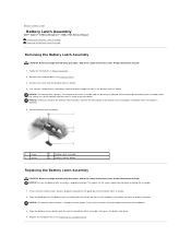
... the base of the battery latch assembly. 2. Ensure that the battery latch spring is ready to Contents Page Battery Latch Assembly Dell™ Vostro™ 1700 and Inspiron™ 1720/1721 Service Manual Removing the Battery Latch Assembly Replacing the Battery Latch Assembly Removing the Battery Latch Assembly CAUTION: Before you begin the following procedure...
... the base of the battery latch assembly. 2. Ensure that the battery latch spring is ready to Contents Page Battery Latch Assembly Dell™ Vostro™ 1700 and Inspiron™ 1720/1721 Service Manual Removing the Battery Latch Assembly Replacing the Battery Latch Assembly Removing the Battery Latch Assembly CAUTION: Before you begin the following procedure...
Service Manual
Page 44
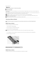
... memory module securing clips. 4. Follow the procedures in the Product Information Guide. Back to Contents Page Memory Dell™ Vostro™ 1700 and Inspiron™ 1720/1721 Service Manual Removing a Memory Module Replacing a Memory Module Your computer has two user-accessible SODIMM sockets, one memory module... of the memory module connector until the module pops up. 5. See "Specifications" in your Owner's Manual for your computer. NOTE: Memory modules purchased from Dell are intended for information on each end of the computer. NOTICE: To prevent damage to the memory ...
... memory module securing clips. 4. Follow the procedures in the Product Information Guide. Back to Contents Page Memory Dell™ Vostro™ 1700 and Inspiron™ 1720/1721 Service Manual Removing a Memory Module Replacing a Memory Module Your computer has two user-accessible SODIMM sockets, one memory module... of the memory module connector until the module pops up. 5. See "Specifications" in your Owner's Manual for your computer. NOTE: Memory modules purchased from Dell are intended for information on each end of the computer. NOTICE: To prevent damage to the memory ...
Service Manual
Page 48
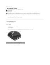
... Mini Card compartment cover, then remove the cover and set it aside. 1 captive screws (2) 2 cover 4. Back to Contents Page Wireless Mini Cards Dell™ Vostro™ 1700 and Inspiron™ 1720/1721 Service Manual Removing a Mini Card Replacing a Mini Card CAUTION: Before you ordered a wireless Mini Card with your computer, the card is already installed.
... Mini Card compartment cover, then remove the cover and set it aside. 1 captive screws (2) 2 cover 4. Back to Contents Page Wireless Mini Cards Dell™ Vostro™ 1700 and Inspiron™ 1720/1721 Service Manual Removing a Mini Card Replacing a Mini Card CAUTION: Before you ordered a wireless Mini Card with your computer, the card is already installed.
Service Manual
Page 54
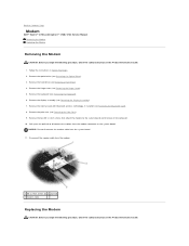
... modem cable from the system board. 11. Remove the palm rest (see Removing the Palm Rest). 9. Back to Contents Page Modem Dell™ Vostro™ 1700 and Inspiron™ 1720/1721 Service Manual Removing the Modem Replacing the Modem Removing the Modem CAUTION: Before you begin the following procedure, follow the safety instructions in the...
... modem cable from the system board. 11. Remove the palm rest (see Removing the Palm Rest). 9. Back to Contents Page Modem Dell™ Vostro™ 1700 and Inspiron™ 1720/1721 Service Manual Removing the Modem Replacing the Modem Removing the Modem CAUTION: Before you begin the following procedure, follow the safety instructions in the...


