
View
Page 28
Enables wireless devices. Scans for WLAN networks (see "Dell Wi-Fi Catcher™ Network Locator" on position 3 momentary position 4 Wi-Fi Catcher light Disables wireless devices. 1 2 34 1 off position 2 on page 94). • Flashing ...: No signal found NOTE: The Wi-Fi Catcher Network Locator light appears only when the system is switched off and Wi-Fi is activated in BIOS. Right Side View 123 11 10 9 8 7 6 54 28 About Your Computer
Enables wireless devices. Scans for WLAN networks (see "Dell Wi-Fi Catcher™ Network Locator" on position 3 momentary position 4 Wi-Fi Catcher light Disables wireless devices. 1 2 34 1 off position 2 on page 94). • Flashing ...: No signal found NOTE: The Wi-Fi Catcher Network Locator light appears only when the system is switched off and Wi-Fi is activated in BIOS. Right Side View 123 11 10 9 8 7 6 54 28 About Your Computer

View
Page 47
...Battery operating time (the time the battery can use the computer. Using a Battery Battery Performance NOTE: For information about the Dell warranty for information about accessing Windows Power Options Properties or Dell QuickSet, which it is used, you may not be fully charged, use the AC adapter to connect your computer to... an electrical outlet when writing to media. For optimal computer performance and to help preserve BIOS settings, operate your Dell™ portable computer with the AC adapter until the battery is fully charged.
...Battery operating time (the time the battery can use the computer. Using a Battery Battery Performance NOTE: For information about the Dell warranty for information about accessing Windows Power Options Properties or Dell QuickSet, which it is used, you may not be fully charged, use the AC adapter to connect your computer to... an electrical outlet when writing to media. For optimal computer performance and to help preserve BIOS settings, operate your Dell™ portable computer with the AC adapter until the battery is fully charged.
View
Page 94
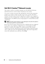
... is disabled and not configured for use Dell QuickSet to enable and configure the switch to control WiFi network connections. For more information on the Wi-Fi Catcher Network Locator and to enable the feature through Dell QuickSet or the BIOS (system setup program) to control WiFi ...network connections. Dell Wi-Fi Catcher™ Network Locator The wireless switch on your Dell computer uses the Dell Wi-Fi Catcher Network Locator to scan for wireless networks...
... is disabled and not configured for use Dell QuickSet to enable and configure the switch to control WiFi network connections. For more information on the Wi-Fi Catcher Network Locator and to enable the feature through Dell QuickSet or the BIOS (system setup program) to control WiFi ...network connections. Dell Wi-Fi Catcher™ Network Locator The wireless switch on your Dell computer uses the Dell Wi-Fi Catcher Network Locator to scan for wireless networks...
View
Page 137
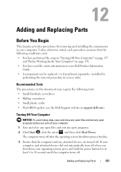
..." on page 137 and "Before Working Inside Your Computer" on page 138. • You have read the safety information in your Dell Product Information Guide. • A component can be replaced-or if purchased separately-installed by performing the removal procedure in your computer. If...3 Ensure that the following tools: • Small flat-blade screwdriver • Phillips screwdriver • Small plastic scribe • Flash BIOS update (see the Dell Support website at least 8 to 10 seconds until the computer turns off. Unless otherwise noted, each procedure assumes that the computer and...
..." on page 137 and "Before Working Inside Your Computer" on page 138. • You have read the safety information in your Dell Product Information Guide. • A component can be replaced-or if purchased separately-installed by performing the removal procedure in your computer. If...3 Ensure that the following tools: • Small flat-blade screwdriver • Phillips screwdriver • Small plastic scribe • Flash BIOS update (see the Dell Support website at least 8 to 10 seconds until the computer turns off. Unless otherwise noted, each procedure assumes that the computer and...
View
Page 196
... between the computer hardware and the operating system. A temperature measurement scale where 0° is the freezing point and 100° is usually equal to once. BIOS - Unless you can be written to 8 bits. Your Drivers and Utilities media is an optical disc format jointly developed by your computer. Specifies the order...
... between the computer hardware and the operating system. A temperature measurement scale where 0° is the freezing point and 100° is usually equal to once. BIOS - Unless you can be written to 8 bits. Your Drivers and Utilities media is an optical disc format jointly developed by your computer. Specifies the order...
View
Page 205
...Express - A modification to create an image. If the PCI Express chip set and the device are capable of pixels across by the BIOS, that is expressed as logical drives. PCMCIA - The organization that boosts the data transfer rate between the processor and the devices attached ..., such as 800 x 600, is assigned to it. Plug and Play provides automatic installation, configuration, and compatibility with existing hardware if the BIOS, operating system, and all devices are detected during POST, the computer continues the start-up and down. power-on the major computer components, ...
...Express - A modification to create an image. If the PCI Express chip set and the device are capable of pixels across by the BIOS, that is expressed as logical drives. PCMCIA - The organization that boosts the data transfer rate between the processor and the devices attached ..., such as 800 x 600, is assigned to it. Plug and Play provides automatic installation, configuration, and compatibility with existing hardware if the BIOS, operating system, and all devices are detected during POST, the computer continues the start-up and down. power-on the major computer components, ...

View
Page 208
... to attach a TV or digital audio device to save energy. Typical SVGA resolutions are 800 x 600 and 1024 x 768. The main circuit board in the BIOS, such as the motherboard. Also known as date and time or system password.
... to attach a TV or digital audio device to save energy. Typical SVGA resolutions are 800 x 600 and 1024 x 768. The main circuit board in the BIOS, such as the motherboard. Also known as date and time or system password.
Service Manual
Page 1
Dell™ Vostro™ 1700 and Inspiron™ 1720/1721 Service Manual Before You Begin ExpressCards Using the Memory Card Reader Optical Drive Hard Drive Hinge Cover Internal Card With Bluetooth® Wireless Technology ... Battery Graphics Card Assembly Processor Thermal-Cooling Assembly Processor Module Fan Speaker Assembly System Board Assembly Computer Base and Components Battery Latch Assembly Flashing the BIOS Pin Assignments for property damage, personal injury, or death. Information in this document is strictly forbidden. All rights reserved. is subject to avoid the problem...
Dell™ Vostro™ 1700 and Inspiron™ 1720/1721 Service Manual Before You Begin ExpressCards Using the Memory Card Reader Optical Drive Hard Drive Hinge Cover Internal Card With Bluetooth® Wireless Technology ... Battery Graphics Card Assembly Processor Thermal-Cooling Assembly Processor Module Fan Speaker Assembly System Board Assembly Computer Base and Components Battery Latch Assembly Flashing the BIOS Pin Assignments for property damage, personal injury, or death. Information in this document is strictly forbidden. All rights reserved. is subject to avoid the problem...
Service Manual
Page 10
... website at support.dell.com) Before Working Inside Your Computer Use the following tools: l Small flat-blade screwdriver l Phillips screwdriver l Small plastic scribe l Flash BIOS update (see Removing a Memory Card or Blank). l You have performed the steps in Before Working Inside Your ... already removed the original, if installed. Disconnect your computer. Back to Contents Page Before You Begin Dell™ Vostro™ 1700 and Inspiron™ 1720/1721 Service Manual Recommended Tools Before Working Inside Your Computer This document provides procedures for removing and installing...
... website at support.dell.com) Before Working Inside Your Computer Use the following tools: l Small flat-blade screwdriver l Phillips screwdriver l Small plastic scribe l Flash BIOS update (see Removing a Memory Card or Blank). l You have performed the steps in Before Working Inside Your ... already removed the original, if installed. Disconnect your computer. Back to Contents Page Before You Begin Dell™ Vostro™ 1700 and Inspiron™ 1720/1721 Service Manual Recommended Tools Before Working Inside Your Computer This document provides procedures for removing and installing...
Service Manual
Page 12
.... Otherwise, you do not have a BIOS-update program CD, flash the BIOS from a CD for your computer at support.dell.com. 4. Press and to boot and updates the new BIOS. Remove the flash BIOS update program CD from the CD. Flashing the BIOS From the Hard Drive NOTICE: Plug the...power source to prevent a loss of power. Back to Contents Page Flashing the BIOS Dell™ Vostro™ 1700 and Inspiron™ 1720/1721 Service Manual Flashing the BIOS From a CD Flashing the BIOS From the Hard Drive If a BIOS-update program CD is complete, the computer will automatically reboot. 3. Doing so ...
.... Otherwise, you do not have a BIOS-update program CD, flash the BIOS from a CD for your computer at support.dell.com. 4. Press and to boot and updates the new BIOS. Remove the flash BIOS update program CD from the CD. Flashing the BIOS From the Hard Drive NOTICE: Plug the...power source to prevent a loss of power. Back to Contents Page Flashing the BIOS Dell™ Vostro™ 1700 and Inspiron™ 1720/1721 Service Manual Flashing the BIOS From a CD Flashing the BIOS From the Hard Drive If a BIOS-update program CD is complete, the computer will automatically reboot. 3. Doing so ...
Service Manual
Page 65
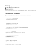
...). 6. Disconnect the cable for transferring the Service Tag to Contents Page System Board Assembly Dell™ Vostro™ 1700 and Inspiron™ 1720/1721 Service Manual Removing the System Board Assembly Replacing the System Board Assembly The system board's BIOS chip contains the Service Tag, which is also visible on a barcode label on the...
...). 6. Disconnect the cable for transferring the Service Tag to Contents Page System Board Assembly Dell™ Vostro™ 1700 and Inspiron™ 1720/1721 Service Manual Removing the System Board Assembly Replacing the System Board Assembly The system board's BIOS chip contains the Service Tag, which is also visible on a barcode label on the...
Service Manual
Page 67
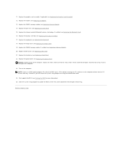
... boot from the CD for more information). 25. Replace the graphics card assembly, if applicable (see Replacing a Memory Module). 20. Flash update the BIOS (see Replacing a Mini Card). 21. Replace the keyboard (see Replacing the Optical Drive). Replace the optical drive (see Replacing the Keyboard). 18. ...Failure to do so may result in order to set the computer to update the BIOS on the new system board with Bluetooth wireless technology, if installed (see Replacing the Bluetooth Card). 16. Replace the internal card with the...
... boot from the CD for more information). 25. Replace the graphics card assembly, if applicable (see Replacing a Memory Module). 20. Flash update the BIOS (see Replacing a Mini Card). 21. Replace the keyboard (see Replacing the Optical Drive). Replace the optical drive (see Replacing the Keyboard). 18. ...Failure to do so may result in order to set the computer to update the BIOS on the new system board with Bluetooth wireless technology, if installed (see Replacing the Bluetooth Card). 16. Replace the internal card with the...


