
Owners Manual
Page 4
... Replacing the Display Panel 43 13 Camera Module 45 Removing the Camera Module 45 Replacing the Camera Module 48 14 System Board 49 Removing the System Board 49 Replacing the System Board 52 Entering the Service Tag in the BIOS 53 15 Thermal-Cooling Assembly 55 Removing the Thermal-Cooling Assembly 55 Replacing...
... Replacing the Display Panel 43 13 Camera Module 45 Removing the Camera Module 45 Replacing the Camera Module 48 14 System Board 49 Removing the System Board 49 Replacing the System Board 52 Entering the Service Tag in the BIOS 53 15 Thermal-Cooling Assembly 55 Removing the Thermal-Cooling Assembly 55 Replacing...
Owners Manual
Page 5
18 Speakers 67 Removing the Speakers 67 Replacing the Speakers 69 19 Media Card Reader 71 Removing the Media Card Reader 71 Replacing the Media Card Reader 73 20 Daughter Board 75 Removing the Daughter Board 75 Replacing the Daughter Board 77 21 Mini-Card 79 Removing the Mini-Card 79 Replacing the Mini-Card 80 22 Flashing the BIOS 83 Contents | 5
18 Speakers 67 Removing the Speakers 67 Replacing the Speakers 69 19 Media Card Reader 71 Removing the Media Card Reader 71 Replacing the Media Card Reader 73 20 Daughter Board 75 Removing the Daughter Board 75 Replacing the Daughter Board 77 21 Mini-Card 79 Removing the Mini-Card 79 Replacing the Mini-Card 80 22 Flashing the BIOS 83 Contents | 5

Owners Manual
Page 7
... connecting to dissipate static electricity, which could harm internal components. Safety Instructions Use the following safety guidelines to ground the system board. For additional safety best practices information, see the documentation of the computer. CAUTION: To avoid damaging the components and cards,... handle them by touching an unpainted metal surface, such as the metal at dell.com/ regulatory_compliance. After you work surface is unplugged, to protect your computer from your computer, ground yourself by their edges...
... connecting to dissipate static electricity, which could harm internal components. Safety Instructions Use the following safety guidelines to ground the system board. For additional safety best practices information, see the documentation of the computer. CAUTION: To avoid damaging the components and cards,... handle them by touching an unpainted metal surface, such as the metal at dell.com/ regulatory_compliance. After you work surface is unplugged, to protect your computer from your computer, ground yourself by their edges...
Owners Manual
Page 16
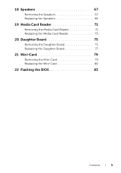
... it on the palm rest. 4 Lift the connector latch and pull the pull-tab to disconnect the keyboard cable from the connector on the system board. 5 Lift the keyboard away from the computer. 1 2 3 1 keyboard cable 3 tabs (5) 2 connector latch Replacing the Keyboard Procedure 1 Slide the keyboard ...cable into the connector on the system board and press down on the connector latch to secure the cable. 2 Slide the tabs at the bottom of the keyboard into the slots on the...
... it on the palm rest. 4 Lift the connector latch and pull the pull-tab to disconnect the keyboard cable from the connector on the system board. 5 Lift the keyboard away from the computer. 1 2 3 1 keyboard cable 3 tabs (5) 2 connector latch Replacing the Keyboard Procedure 1 Slide the keyboard ...cable into the connector on the system board and press down on the connector latch to secure the cable. 2 Slide the tabs at the bottom of the keyboard into the slots on the...

Owners Manual
Page 22
Procedure 1 Remove the screws that secure the hard-drive assembly to the computer base. 2 Using the pull-tab, slide the hard-drive assembly toward the back of the computer to disconnect the hard-drive assembly from the connector on the system board. 3 Lift the hard-drive assembly out of the computer base. 1 2 3 1 pull-tab 3 hard-drive assembly 2 screws (4) 22 | Hard Drive
Procedure 1 Remove the screws that secure the hard-drive assembly to the computer base. 2 Using the pull-tab, slide the hard-drive assembly toward the back of the computer to disconnect the hard-drive assembly from the connector on the system board. 3 Lift the hard-drive assembly out of the computer base. 1 2 3 1 pull-tab 3 hard-drive assembly 2 screws (4) 22 | Hard Drive

Owners Manual
Page 23
... pull-tab, slide the hard-drive assembly toward the front of the computer, to connect the hard-drive assembly to the connector on the system board. 6 Replace the screws that secure the hard-drive bracket to the computer base. Hard Drive | 23
... pull-tab, slide the hard-drive assembly toward the front of the computer, to connect the hard-drive assembly to the connector on the system board. 6 Replace the screws that secure the hard-drive bracket to the computer base. Hard Drive | 23

Owners Manual
Page 28
2 Turn the computer over. 3 Lift the connector latches and pull the pull-tabs to disconnect the power-button board cable, touchpad cable, and hot-key board cable from the connectors on the system board. 12 34 5 1 power-button board cable 3 connector latch 5 hot-key board cable 2 pull-tab 4 touchpad cable 28 | Palm Rest
2 Turn the computer over. 3 Lift the connector latches and pull the pull-tabs to disconnect the power-button board cable, touchpad cable, and hot-key board cable from the connectors on the system board. 12 34 5 1 power-button board cable 3 connector latch 5 hot-key board cable 2 pull-tab 4 touchpad cable 28 | Palm Rest

Owners Manual
Page 30
6 Without pulling hard on the palm-rest assembly, place it away from the display as shown in the illustration below. 7 Lift the connector latch and pull the pull-tab to disconnect the status-lights cable from the connector on the system board. 8 Lift the palm-rest assembly off the computer base. 12 3 1 connector latch 3 status-lights cable 2 pull-tab 30 | Palm Rest
6 Without pulling hard on the palm-rest assembly, place it away from the display as shown in the illustration below. 7 Lift the connector latch and pull the pull-tab to disconnect the status-lights cable from the connector on the system board. 8 Lift the palm-rest assembly off the computer base. 12 3 1 connector latch 3 status-lights cable 2 pull-tab 30 | Palm Rest
Owners Manual
Page 31
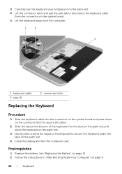
... that secure the palm rest to the computer base. Replacing the Palm Rest Procedure 1 Slide the status-lights cable into the connector on the system board and press down on the connector latch to secure the cable. 2 Align the palm rest with the computer base and gently snap the palm rest... into place. 3 Slide the hot-key board cable, power-button board cable, and touchpad cable into the connectors on the system board and press down on page 18. 2 Replace the keyboard.
... that secure the palm rest to the computer base. Replacing the Palm Rest Procedure 1 Slide the status-lights cable into the connector on the system board and press down on the connector latch to secure the cable. 2 Align the palm rest with the computer base and gently snap the palm rest... into place. 3 Slide the hot-key board cable, power-button board cable, and touchpad cable into the connectors on the system board and press down on page 18. 2 Replace the keyboard.
Owners Manual
Page 34
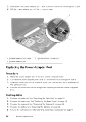
... the battery. 3 Disconnect the power-adapter port cable from the connector on the system board. 4 Lift the power-adapter port off the computer base. 1 2 3 1 power-adapter port cable 3 power-adapter port 2 system-board connector Replacing the Power-Adapter Port Procedure 1 Place the power-adapter port in "After Working... 13. 5 Follow the instructions in the slot on the computer base. 2 Connect the power-adapter port cable to the connector on the system board. 3 Align the screw holes on the power-adapter port bracket with the screw holes on page 31. 2 Replace the base cover. See "...
... the battery. 3 Disconnect the power-adapter port cable from the connector on the system board. 4 Lift the power-adapter port off the computer base. 1 2 3 1 power-adapter port cable 3 power-adapter port 2 system-board connector Replacing the Power-Adapter Port Procedure 1 Place the power-adapter port in "After Working... 13. 5 Follow the instructions in the slot on the computer base. 2 Connect the power-adapter port cable to the connector on the system board. 3 Align the screw holes on the power-adapter port bracket with the screw holes on page 31. 2 Replace the base cover. See "...

Owners Manual
Page 36
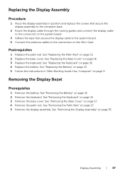
Procedure 1 Disconnect the antenna cables from the connectors on the Mini-Card. 2 Peel the tape that secures the display cable to the system board and then disconnect the display cable from the connector on the system board. 3 Make a note of the display cable routing and remove the cable from the routing guides. 4 Remove the screws that secure the display assembly to the computer base. 5 Lift the display assembly off the computer base. 5 1 2 4 3 1 display assembly 3 tape 5 antenna cables (2) 2 screws (6) 4 display cable 36 | Display Assembly
Procedure 1 Disconnect the antenna cables from the connectors on the Mini-Card. 2 Peel the tape that secures the display cable to the system board and then disconnect the display cable from the connector on the system board. 3 Make a note of the display cable routing and remove the cable from the routing guides. 4 Remove the screws that secure the display assembly to the computer base. 5 Lift the display assembly off the computer base. 5 1 2 4 3 1 display assembly 3 tape 5 antenna cables (2) 2 screws (6) 4 display cable 36 | Display Assembly
Owners Manual
Page 37
... base. 2 Route the display cable through the routing guides and connect the display cable to the connector on the system board. 3 Adhere the tape that secures the display cable to the system board. 4 Connect the antenna cables to the connectors on the Mini-Card. Postrequisites 1 Replace the palm rest. Replacing the Display...
... base. 2 Route the display cable through the routing guides and connect the display cable to the connector on the system board. 3 Adhere the tape that secures the display cable to the system board. 4 Connect the antenna cables to the connectors on the Mini-Card. Postrequisites 1 Replace the palm rest. Replacing the Display...

Owners Manual
Page 42
3 Peel and lift the tape that secures the display cable to the display-board connector and disconnect the display cable. 4 Peel the display cable from the back of the display panel. 1 3 2 1 display cable 3 tape 2 display-board connector 42 | Display Assembly
3 Peel and lift the tape that secures the display cable to the display-board connector and disconnect the display cable. 4 Peel the display cable from the back of the display panel. 1 3 2 1 display cable 3 tape 2 display-board connector 42 | Display Assembly

Owners Manual
Page 43
... display panel. 2 Turn the display panel over. 3 Adhere the display cable to the back of the display panel. 4 Connect the display cable to the display-board connector and secure it with the tape. 5 Align the screw holes on the display panel with the screw holes on the display cover and replace...
... display panel. 2 Turn the display panel over. 3 Adhere the display cable to the back of the display panel. 4 Connect the display cable to the display-board connector and secure it with the tape. 5 Align the screw holes on the display panel with the screw holes on the display cover and replace...

Owners Manual
Page 49
...page 25. 6 Remove the keyboard. For additional safety best practices information, see the Regulatory Compliance Homepage at dell.com/regulatory_compliance. Removing the System Board Prerequisites 1 Remove the battery. System Board | 49 See "Removing the Base Cover" on page 13. 2 Remove the base cover. See "Removing... the Battery" on page 17. 3 Remove the memory module(s). 14 System Board WARNING: Before working inside your computer, read the safety information that shipped with your computer and follow the steps in "Removing the Optical...
...page 25. 6 Remove the keyboard. For additional safety best practices information, see the Regulatory Compliance Homepage at dell.com/regulatory_compliance. Removing the System Board Prerequisites 1 Remove the battery. System Board | 49 See "Removing the Base Cover" on page 13. 2 Remove the base cover. See "Removing... the Battery" on page 17. 3 Remove the memory module(s). 14 System Board WARNING: Before working inside your computer, read the safety information that shipped with your computer and follow the steps in "Removing the Optical...

Owners Manual
Page 50
NOTE: Before disconnecting the cables from the system board, note the location of the connectors so that secure the power-adapter port bracket to the computer base. 2 Lift the power-adapter port bracket off the computer base. 1 2 1 screws (2) 2 power-adapter port bracket 50 | System Board You must enter the Service Tag in the system board. Procedure NOTE: Your computer's Service Tag is stored in the BIOS after you replace the system-board assembly. 1 Remove the screws that you can reconnect them correctly after you replace the system-board assembly.
NOTE: Before disconnecting the cables from the system board, note the location of the connectors so that secure the power-adapter port bracket to the computer base. 2 Lift the power-adapter port bracket off the computer base. 1 2 1 screws (2) 2 power-adapter port bracket 50 | System Board You must enter the Service Tag in the system board. Procedure NOTE: Your computer's Service Tag is stored in the BIOS after you replace the system-board assembly. 1 Remove the screws that you can reconnect them correctly after you replace the system-board assembly.
Owners Manual
Page 51
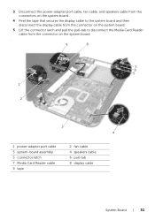
3 Disconnect the power-adapter port cable, fan cable, and speakers cable from the connectors on the system board. 4 Peel the tape that secures the display cable to the system board and then disconnect the display cable from the connector on the system board. 5 Lift the connector latch and pull the pull-tab to disconnect the Media Card Reader cable from the connector on the system board. . 9 8 7 6 5 1 2 3 4 1 power-adapter port cable 3 system-board assembly 5 connector latch 7 Media Card Reader cable 9 tape 2 fan cable 4 speakers cable 6 pull-tab 8 display cable System Board | 51
3 Disconnect the power-adapter port cable, fan cable, and speakers cable from the connectors on the system board. 4 Peel the tape that secures the display cable to the system board and then disconnect the display cable from the connector on the system board. 5 Lift the connector latch and pull the pull-tab to disconnect the Media Card Reader cable from the connector on the system board. . 9 8 7 6 5 1 2 3 4 1 power-adapter port cable 3 system-board assembly 5 connector latch 7 Media Card Reader cable 9 tape 2 fan cable 4 speakers cable 6 pull-tab 8 display cable System Board | 51

Owners Manual
Page 52
... press the system board to connect the connector on the system board to the connector on the daughter board. 5 Replace the screws that secure the system board to the computer base. 7 Lift the system board to the computer base. 52 | System Board Replacing the System Board Procedure 1 Replace the... screws that secure the system board to disconnect the connector on the system board from the connector on the daughter board. 8 Lift the system board at an angle and release the connectors on the system board from the slots on the computer base. 2 1 1 system-board assembly 2 screws (6) 9 ...
... press the system board to connect the connector on the system board to the connector on the daughter board. 5 Replace the screws that secure the system board to the computer base. 7 Lift the system board to the computer base. 52 | System Board Replacing the System Board Procedure 1 Replace the... screws that secure the system board to disconnect the connector on the system board from the connector on the daughter board. 8 Lift the system board at an angle and release the connectors on the system board from the slots on the computer base. 2 1 1 system-board assembly 2 screws (6) 9 ...
Owners Manual
Page 53
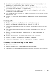
... on the computer. 2 Press during POST to enter the system setup program. 3 Navigate to the computer base. System Board | 53 6 Slide the Media Card Reader cable into the connector on the system board and press down on the connector latch to secure the cable. 7 Connect the display cable to the connector on... the power-adapter port cable, fan cable, and speakers cable to the connectors on the system board. 9 Align the screw holes on the power-adapter port bracket with the screw holes on the computer base. 10 Replace the screws that secure the ...
... on the computer. 2 Press during POST to enter the system setup program. 3 Navigate to the computer base. System Board | 53 6 Slide the Media Card Reader cable into the connector on the system board and press down on the connector latch to secure the cable. 7 Connect the display cable to the connector on... the power-adapter port cable, fan cable, and speakers cable to the connectors on the system board. 9 Align the screw holes on the power-adapter port bracket with the screw holes on the computer base. 10 Replace the screws that secure the ...

Owners Manual
Page 55
..."Removing the Keyboard" on page 17. 3 Remove the memory module(s). For additional safety best practices information, see the Regulatory Compliance Homepage at dell.com/regulatory_compliance. 15 Thermal-Cooling Assembly WARNING: Before working inside your computer, read the safety information that shipped with your computer and follow the... | 55 See "Removing the Palm Rest" on page 27. 8 Follow the instructions from step 1 to step 8 in "Removing the System Board" on page 49. Removing the Thermal-Cooling Assembly Prerequisites 1 Remove the battery. See "Removing the Battery" on page 7.
..."Removing the Keyboard" on page 17. 3 Remove the memory module(s). For additional safety best practices information, see the Regulatory Compliance Homepage at dell.com/regulatory_compliance. 15 Thermal-Cooling Assembly WARNING: Before working inside your computer, read the safety information that shipped with your computer and follow the... | 55 See "Removing the Palm Rest" on page 27. 8 Follow the instructions from step 1 to step 8 in "Removing the System Board" on page 49. Removing the Thermal-Cooling Assembly Prerequisites 1 Remove the battery. See "Removing the Battery" on page 7.


