
User Guide
Page 4
... 43 Replacing the I/O Panel 44 Drives 45 General Installation Guidelines 45 IDE Drive Addressing 46 Connecting Drive Cables 46 Drive Interface Connectors 46 Power Cable Connectors 47 Connecting and Disconnecting Drive Cables 47 Hard Drive 48 Removing a Hard Drive 48 Installing a Hard Drive 49 Adding a...73 Removing a PCI Express Card 77 Serial Port Adapters 78 Installing a Serial Port Adapter 78 Removing a Serial Port Adapter 80 Power Supply 83 Replacing the Power Supply 83 DC Power Connectors 85 Processor 91 Removing the Processor 91 Installing the Processor 92 4 Contents
... 43 Replacing the I/O Panel 44 Drives 45 General Installation Guidelines 45 IDE Drive Addressing 46 Connecting Drive Cables 46 Drive Interface Connectors 46 Power Cable Connectors 47 Connecting and Disconnecting Drive Cables 47 Hard Drive 48 Removing a Hard Drive 48 Installing a Hard Drive 49 Adding a...73 Removing a PCI Express Card 77 Serial Port Adapters 78 Installing a Serial Port Adapter 78 Removing a Serial Port Adapter 80 Power Supply 83 Replacing the Power Supply 83 DC Power Connectors 85 Processor 91 Removing the Processor 91 Installing the Processor 92 4 Contents
User Guide
Page 6
... Adapter 140 Installing a Serial Port Adapter in the Riser-Card Cage . . . 141 Removing a Serial Port Adapter From the Riser-Card Cage 142 Power Supply 145 Replacing the Power Supply 145 DC Power Connectors 147 Processor 153 Removing the Processor 153 Installing the Processor 154 6 Small Form Factor Computer About Your Small Form Factor Computer 157...
... Adapter 140 Installing a Serial Port Adapter in the Riser-Card Cage . . . 141 Removing a Serial Port Adapter From the Riser-Card Cage 142 Power Supply 145 Replacing the Power Supply 145 DC Power Connectors 147 Processor 153 Removing the Processor 153 Installing the Processor 154 6 Small Form Factor Computer About Your Small Form Factor Computer 157...

User Guide
Page 7
Power Cable Connectors 176 Connecting and Disconnecting Drive Cables 177 Hard Drive 177 Removing a Hard Drive 177 Installing a Hard Drive 179 CD/DVD Drive 182 Removing a ... 189 Installing a PCI Express Card 189 Removing a PCI Express Card 193 Serial Port Adapters 193 Installing a Serial Port Adapter 194 Removing a Serial Port Adapter 194 Power Supply 195 Processor 197 Removing the Processor 197 Installing the Processor 198 7 Ultra Small Form Factor Computer About Your Ultra Small Form Factor Computer 201 Front...
Power Cable Connectors 176 Connecting and Disconnecting Drive Cables 177 Hard Drive 177 Removing a Hard Drive 177 Installing a Hard Drive 179 CD/DVD Drive 182 Removing a ... 189 Installing a PCI Express Card 189 Removing a PCI Express Card 193 Serial Port Adapters 193 Installing a Serial Port Adapter 194 Removing a Serial Port Adapter 194 Power Supply 195 Processor 197 Removing the Processor 197 Installing the Processor 198 7 Ultra Small Form Factor Computer About Your Ultra Small Form Factor Computer 201 Front...
User Guide
Page 31
www.dell.com | support.dell.com 3 2 1 4 5 6 7 1 CD/DVD drive 2 floppy drive 3 power supply 4 chassis intrusion switch 5 system board 6 heat sink assembly 7 hard drive 31 Mini Tower Computer
www.dell.com | support.dell.com 3 2 1 4 5 6 7 1 CD/DVD drive 2 floppy drive 3 power supply 4 chassis intrusion switch 5 system board 6 heat sink assembly 7 hard drive 31 Mini Tower Computer
User Guide
Page 38
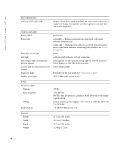
...for a 1000-Mb (1-Gb) operation yellow blinking light Four lights on the back panel. See "Diagnostic Lights." AUX_PWR on state. manual selection power supplies-90 to 135 V at 50/60 Hz 3-V CR2032 lithium coin cell Physical Height Width Depth Weight 41.4 cm (16.3 inches) 18.5 cm...Mb operation; Blinking green indicates sleep mode; solid amber indicates an internal power problem (see "Power Problems"). green solid green light indicates network connection green light for 10-Mb operation; www.dell.com | support.dell.com Key Combinations or displays a boot device menu that allows the ...
...for a 1000-Mb (1-Gb) operation yellow blinking light Four lights on the back panel. See "Diagnostic Lights." AUX_PWR on state. manual selection power supplies-90 to 135 V at 50/60 Hz 3-V CR2032 lithium coin cell Physical Height Width Depth Weight 41.4 cm (16.3 inches) 18.5 cm...Mb operation; Blinking green indicates sleep mode; solid amber indicates an internal power problem (see "Power Problems"). green solid green light indicates network connection green light for 10-Mb operation; www.dell.com | support.dell.com Key Combinations or displays a boot device menu that allows the ...

User Guide
Page 83
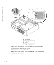
You can do so by touching an unpainted metal surface on the floor of the computer chassis. 83 Note the routing of the DC power cables underneath the tabs in the computer chassis as you touch any of the computer chassis. 4 Press the release button located on the computer chassis. 1 ... cables properly when you begin any of your body before you remove them from being pinched or crimped. 3 Remove the four screws that attach the power supply to the back of the procedures in this section, follow the safety instructions located in "Before You Begin." 2 Disconnect the DC...
You can do so by touching an unpainted metal surface on the floor of the computer chassis. 83 Note the routing of the DC power cables underneath the tabs in the computer chassis as you touch any of the computer chassis. 4 Press the release button located on the computer chassis. 1 ... cables properly when you begin any of your body before you remove them from being pinched or crimped. 3 Remove the four screws that attach the power supply to the back of the procedures in this section, follow the safety instructions located in "Before You Begin." 2 Disconnect the DC...

User Guide
Page 84
www.dell.com | support.dell.com 1 3 2 4 1 release button 2 power supply 3 screws (4) 4 AC power connector 5 Slide the power supply toward the front of the computer by approximately 1 inch. 6 Lift the power supply up and out of the computer. 7 Slide the replacement power supply into place. 8 Replace the screws that secure the power supply to the back of the computer chassis. 9 Reconnect the DC power cables to the power supply. 84
www.dell.com | support.dell.com 1 3 2 4 1 release button 2 power supply 3 screws (4) 4 AC power connector 5 Slide the power supply toward the front of the computer by approximately 1 inch. 6 Lift the power supply up and out of the computer. 7 Slide the replacement power supply into place. 8 Replace the screws that secure the power supply to the back of the computer chassis. 9 Reconnect the DC power cables to the power supply. 84

User Guide
Page 101
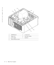
2 1 3 4 5 7 6 1 drives bay (CD/DVD, floppy, 5 card slots and hard drive) 2 power supply 6 heat sink assembly 3 chassis intrusion switch 7 front I/O panel 4 system board Desktop Computer 101
2 1 3 4 5 7 6 1 drives bay (CD/DVD, floppy, 5 card slots and hard drive) 2 power supply 6 heat sink assembly 3 chassis intrusion switch 7 front I/O panel 4 system board Desktop Computer 101
User Guide
Page 109
... (on integrated network adapter) Diagnostic lights Standby power light green solid green light indicates network connection green light for a 1000-Mb (1-Gb) operation yellow blinking light Four lights on the system board Power DC power supply: Wattage Heat dissipation Voltage Backup battery 280 W... 956 BTU/hr NOTE: Heat dissipation is calculated based upon the power supply wattage rating. orange light for 100-Mb operation; See "Diagnostic ...
... (on integrated network adapter) Diagnostic lights Standby power light green solid green light indicates network connection green light for a 1000-Mb (1-Gb) operation yellow blinking light Four lights on the system board Power DC power supply: Wattage Heat dissipation Voltage Backup battery 280 W... 956 BTU/hr NOTE: Heat dissipation is calculated based upon the power supply wattage rating. orange light for 100-Mb operation; See "Diagnostic ...

User Guide
Page 145
...of the procedures in this section, follow the safety instructions located in "Before You Begin." 2 Disconnect the DC power cables from the system board and drives. Power Supply Replacing the Power Supply CAUTION: Before you remove them to prevent their being pinched or crimped. 3 Remove the two screws that attach the... power supply to components inside your computer, discharge static electricity from your computer's electronic components. You must route these cables properly when ...
...of the procedures in this section, follow the safety instructions located in "Before You Begin." 2 Disconnect the DC power cables from the system board and drives. Power Supply Replacing the Power Supply CAUTION: Before you remove them to prevent their being pinched or crimped. 3 Remove the two screws that attach the... power supply to components inside your computer, discharge static electricity from your computer's electronic components. You must route these cables properly when ...
User Guide
Page 146
www.dell.com | support.dell.com 1 23 4 1 release button 2 power supply 3 screws (2) 4 AC power connector 6 Slide the power supply toward the front of the computer by approximately 1 inch. 7 Lift the power supply up and out of the computer. 8 Slide the replacement power supply into place. 9 Replace the screws that secure the power supply to the back of the computer chassis. 10 Reconnect the DC power cables. 146
www.dell.com | support.dell.com 1 23 4 1 release button 2 power supply 3 screws (2) 4 AC power connector 6 Slide the power supply toward the front of the computer by approximately 1 inch. 7 Lift the power supply up and out of the computer. 8 Slide the replacement power supply into place. 9 Replace the screws that secure the power supply to the back of the computer chassis. 10 Reconnect the DC power cables. 146

User Guide
Page 161
NOTICE: Be careful when opening the computer cover to ensure that you do not accidentally disconnect cables from the system board. 3 4 2 1 5 6 1 drive release latch 2 CD/DVD drive 3 power supply and fan 4 hard drive 5 system board 6 heat sink and blower assembly Small Form Factor Computer 161
NOTICE: Be careful when opening the computer cover to ensure that you do not accidentally disconnect cables from the system board. 3 4 2 1 5 6 1 drive release latch 2 CD/DVD drive 3 power supply and fan 4 hard drive 5 system board 6 heat sink and blower assembly Small Form Factor Computer 161
User Guide
Page 168
... 149°F) 20% to 80% (noncondensing) 168 See "Diagnostic Lights." www.dell.com | support.dell.com Controls and Lights Power light Hard-drive access light Link light Link integrity light (on integrated network adapter) Activity light (on the system board Power DC power supply: Wattage Heat dissipation Voltage Backup battery 275 W 939 BTU/hr NOTE: Heat...
... 149°F) 20% to 80% (noncondensing) 168 See "Diagnostic Lights." www.dell.com | support.dell.com Controls and Lights Power light Hard-drive access light Link light Link integrity light (on integrated network adapter) Activity light (on the system board Power DC power supply: Wattage Heat dissipation Voltage Backup battery 275 W 939 BTU/hr NOTE: Heat...

User Guide
Page 195
...into place. 10 Replace the screws that secure the power supply to the back of your computer and devices to the power supply AC power connector. Power Supply CAUTION: Before you begin any of the computer chassis. 11 Reconnect the DC power cables to the system board and drives (see "... 6 Remove the three screws that attach the power supply to the back of the computer chassis. 7 Slide the power supply toward the front of the computer approximately 1 inch. 8 Lift the power supply up and out of the computer. 9 Slide the replacement power supply into the computer. 16 Connect your computer's ...
...into place. 10 Replace the screws that secure the power supply to the back of your computer and devices to the power supply AC power connector. Power Supply CAUTION: Before you begin any of the computer chassis. 11 Reconnect the DC power cables to the system board and drives (see "... 6 Remove the three screws that attach the power supply to the back of the computer chassis. 7 Slide the power supply toward the front of the computer approximately 1 inch. 8 Lift the power supply up and out of the computer. 9 Slide the replacement power supply into the computer. 16 Connect your computer's ...
User Guide
Page 215
...integrated network adapter) Activity light (on the system board Power DC power supply Wattage Heat dissipation 220-W external supply 751 BTU/hr NOTE: Heat dissipation is connected to an AC outlet and the computer. yellow light for a single boot (during system start-up the Windows Security window; Blinking green indicates a sleep mode; amber light ... computer from the network environment specified by the remote boot environment (PXE) rather than from one of the devices in Microsoft® Windows® XP, brings up only) as well as options to an AC outlet but not the computer.
...integrated network adapter) Activity light (on the system board Power DC power supply Wattage Heat dissipation 220-W external supply 751 BTU/hr NOTE: Heat dissipation is connected to an AC outlet and the computer. yellow light for a single boot (during system start-up the Windows Security window; Blinking green indicates a sleep mode; amber light ... computer from the network environment specified by the remote boot environment (PXE) rather than from one of the devices in Microsoft® Windows® XP, brings up only) as well as options to an AC outlet but not the computer.

User Guide
Page 216
www.dell.com | support.dell.com Power Voltage Backup battery Physical Without cable cover: Height Width Depth Weight With standard cable cover: Height Width Depth Weight With extended cable cover: Height Width Depth Environmental Temperature: Operating Storage Relative humidity Maximum vibration: Operating Storage Maximum shock: Operating Storage 216 auto-sensing power supplies - 90 to 135 V at...
www.dell.com | support.dell.com Power Voltage Backup battery Physical Without cable cover: Height Width Depth Weight With standard cable cover: Height Width Depth Weight With extended cable cover: Height Width Depth Environmental Temperature: Operating Storage Relative humidity Maximum vibration: Operating Storage Maximum shock: Operating Storage 216 auto-sensing power supplies - 90 to 135 V at...

User Guide
Page 229
... toward each other, slide the drive slightly forward, and rotate the hard drive up your files before you touch any of your computer from the power supply before removing the hard drive. You can do not set the drive on a hard surface.
... toward each other, slide the drive slightly forward, and rotate the hard drive up your files before you touch any of your computer from the power supply before removing the hard drive. You can do not set the drive on a hard surface.

User Guide
Page 239
... Temperature Problem Cleared The computer temperature is provided to the administrator through system setup, Dell OpenManage™ IT Assistant, or Dell custom factory integration. Manageability Alert Standard Format ASF is designed to electronically activate or deactivate...dell.com | support.dell.com Advanced Features LegacySelect Technology Control LegacySelect technology control offers legacy-full, legacy-reduced, or legacy-free solutions based on potential security and fault conditions when the operating system is in a sleep mode or the system is too hot and the power supply...
... Temperature Problem Cleared The computer temperature is provided to the administrator through system setup, Dell OpenManage™ IT Assistant, or Dell custom factory integration. Manageability Alert Standard Format ASF is designed to electronically activate or deactivate...dell.com | support.dell.com Advanced Features LegacySelect Technology Control LegacySelect technology control offers legacy-full, legacy-reduced, or legacy-free solutions based on potential security and fault conditions when the operating system is in a sleep mode or the system is too hot and the power supply...

User Guide
Page 311
... infected, the boot virus may also provide voltage regulation. If the computer is no electrical power. password. T E X T E D I O N - U UPS - uninterruptible power supply - Describes a type of unshielded wires are plugged directly in computers with an integrated video ...starts, its embedded virus also starts. T R A V E L M O D U L E - A UPS keeps a computer running for example, Windows Notepad uses a text editor. USB - ultra extended graphics array - See resolution. volt - telephony application programming interface - for a limited amount of wires...
... infected, the boot virus may also provide voltage regulation. If the computer is no electrical power. password. T E X T E D I O N - U UPS - uninterruptible power supply - Describes a type of unshielded wires are plugged directly in computers with an integrated video ...starts, its embedded virus also starts. T R A V E L M O D U L E - A UPS keeps a computer running for example, Windows Notepad uses a text editor. USB - ultra extended graphics array - See resolution. volt - telephony application programming interface - for a limited amount of wires...
User Guide
Page 316
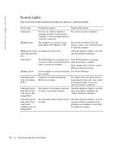
... corrective action is in a power-saving mode (Microsoft® Windows® XP). Blinking green The computer is required. Solid yellow The Dell Diagnostics is running a test, If the Dell Diagnostics is operating normally. has occurred. Solid green power light and no beep code...See "Beep Codes" for technical assistance. On the desktop computer, a solid green light indicates a network connection. Blinking yellow A power supply or system board failure See "Power Problems." Power Light Problem Description Suggested Resolution Solid green Power is on, and the computer is running, or ...
... corrective action is in a power-saving mode (Microsoft® Windows® XP). Blinking green The computer is required. Solid yellow The Dell Diagnostics is running a test, If the Dell Diagnostics is operating normally. has occurred. Solid green power light and no beep code...See "Beep Codes" for technical assistance. On the desktop computer, a solid green light indicates a network connection. Blinking yellow A power supply or system board failure See "Power Problems." Power Light Problem Description Suggested Resolution Solid green Power is on, and the computer is running, or ...


