
Quick Reference Guide
Page 7
Front View 12 3 23 22 25 24 21 20 19 18 1 camera and microphone (optional) 3 display 4 5 6 9 A 7 8 9 10 11 12 14 13 15 16 17 2 display latch 4 keyboard status lights About Your Computer 7 About Your Computer NOTE: For more information about the features of your computer, see the Dell™ Technology Guide on your computer or at support.dell.com.
Front View 12 3 23 22 25 24 21 20 19 18 1 camera and microphone (optional) 3 display 4 5 6 9 A 7 8 9 10 11 12 14 13 15 16 17 2 display latch 4 keyboard status lights About Your Computer 7 About Your Computer NOTE: For more information about the features of your computer, see the Dell™ Technology Guide on your computer or at support.dell.com.
Quick Reference Guide
Page 8
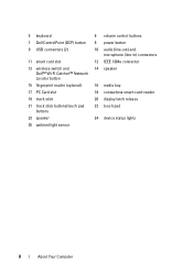
5 keyboard 7 Dell ControlPoint (DCP) button 9 USB connectors (2) 11 smart card slot 13 wireless switch and Dell™ Wi-Fi Catcher™ Network Locator button 15 fingerprint reader (optional) 17 PC Card slot 19 track stick 21 track stick buttons/touch pad buttons 23 speaker 25 ambient light sensor 6 volume control buttons 8 power button 10 audio (line-out) and microphone (line-in) connectors 12 IEEE 1394a connector 14 speaker 16 media bay 18 contactless smart-card-reader 20 display latch release 22 touch pad 24 device status lights 8 About Your Computer
5 keyboard 7 Dell ControlPoint (DCP) button 9 USB connectors (2) 11 smart card slot 13 wireless switch and Dell™ Wi-Fi Catcher™ Network Locator button 15 fingerprint reader (optional) 17 PC Card slot 19 track stick 21 track stick buttons/touch pad buttons 23 speaker 25 ambient light sensor 6 volume control buttons 8 power button 10 audio (line-out) and microphone (line-in) connectors 12 IEEE 1394a connector 14 speaker 16 media bay 18 contactless smart-card-reader 20 display latch release 22 touch pad 24 device status lights 8 About Your Computer

Quick Reference Guide
Page 14
2 Connect the network cable. 3 Connect USB devices, such as a mouse or keyboard. 4 Connect IEEE 1394 devices, such as a DVD player 14 Setting Up Your Computer
2 Connect the network cable. 3 Connect USB devices, such as a mouse or keyboard. 4 Connect IEEE 1394 devices, such as a DVD player 14 Setting Up Your Computer
Quick Reference Guide
Page 28
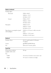
...; WXGA+: 45/45° WUXGA: 45/45° WXGA: 0.2373 WXGA+: 0.2109 WUXGA: 0.1725 WXGA: 6.2 W (max.) with no inverter losses WXGA+: 5.8 W (max.) WUXGA: 13.0 W (max.) Keyboard Number of keys Layout Size 83 (U.S.
...; WXGA+: 45/45° WUXGA: 45/45° WXGA: 0.2373 WXGA+: 0.2109 WUXGA: 0.1725 WXGA: 6.2 W (max.) with no inverter losses WXGA+: 5.8 W (max.) WUXGA: 13.0 W (max.) Keyboard Number of keys Layout Size 83 (U.S.

Quick Reference Guide
Page 33
... power lights are : Power light behavior Indication Off The computer is either turned off or is connected and probably not powered not responding on the keyboard, move the mouse, or press the power button to indicate different states. Steady amber There may be malfunctioning or incorrectly installed. Troubleshooting 33 Tools Power...
... power lights are : Power light behavior Indication Off The computer is either turned off or is connected and probably not powered not responding on the keyboard, move the mouse, or press the power button to indicate different states. Steady amber There may be malfunctioning or incorrectly installed. Troubleshooting 33 Tools Power...
Quick Reference Guide
Page 37
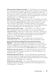
...L U R E - K E Y B O A R D D A T A L I N E F A I L U R E - For external keyboards, check the cable connection. Run the Hard Disk Drive tests in the Dell Diagnostics (see "Dell Diagnostics" on page 42). Then, shut down the computer, reinstall the hard drive, and restart the computer. Run...hard drive, and restart the computer. Run the Hard Disk Drive tests in the Dell Diagnostics (see "Dell Diagnostics" on page 42). Run the Keyboard Controller test in the Dell Diagnostics (see "Dell Diagnostics" on page 42). Troubleshooting 37 If the problem persists, try another drive...
...L U R E - K E Y B O A R D D A T A L I N E F A I L U R E - For external keyboards, check the cable connection. Run the Hard Disk Drive tests in the Dell Diagnostics (see "Dell Diagnostics" on page 42). Then, shut down the computer, reinstall the hard drive, and restart the computer. Run...hard drive, and restart the computer. Run the Hard Disk Drive tests in the Dell Diagnostics (see "Dell Diagnostics" on page 42). Run the Keyboard Controller test in the Dell Diagnostics (see "Dell Diagnostics" on page 42). Troubleshooting 37 If the problem persists, try another drive...

Quick Reference Guide
Page 38
...more information. See your Service Manual at support.dell.com for more information. See your boot device, ensure that the drive is conflicting with the operating system, another program, or a utility. N O B O O T D E V I C E A V A I O N E R R O R - For external keyboards or keypads, check the cable connection. MEMORY ...memory module may be faulty or improperly seated. A memory module may be played (see "Dell Diagnostics" on page 42). Restart the computer, and avoid touching the keyboard or keys during the boot routine. Shut down the computer, wait 30 seconds, and then...
...more information. See your Service Manual at support.dell.com for more information. See your boot device, ensure that the drive is conflicting with the operating system, another program, or a utility. N O B O O T D E V I C E A V A I O N E R R O R - For external keyboards or keypads, check the cable connection. MEMORY ...memory module may be faulty or improperly seated. A memory module may be played (see "Dell Diagnostics" on page 42). Restart the computer, and avoid touching the keyboard or keys during the boot routine. Shut down the computer, wait 30 seconds, and then...
Quick Reference Guide
Page 40
.... SHUTDOWN FAILURE - A chip on page 42). System configuration settings are corrupted. Connect your Service Manual at support.dell.com). WA R N I N G : B A T T E R Y I S C R I T I L E D - OF - TIME- Run the System Memory tests and the Keyboard Controller test in the Dell Diagnostics (see "Dell Diagnostics" on the system board may be malfunctioning. X : \ I S N O T A C C E S S I N P R O T E C T E D M O D E - O F - U N E X P E C T E D I N T E R R U P T I B L E . Run the System Set tests in the system...
.... SHUTDOWN FAILURE - A chip on page 42). System configuration settings are corrupted. Connect your Service Manual at support.dell.com). WA R N I N G : B A T T E R Y I S C R I T I L E D - OF - TIME- Run the System Memory tests and the Keyboard Controller test in the Dell Diagnostics (see "Dell Diagnostics" on the system board may be malfunctioning. X : \ I S N O T A C C E S S I N P R O T E C T E D M O D E - O F - U N E X P E C T E D I N T E R R U P T I B L E . Run the System Set tests in the system...
Quick Reference Guide
Page 41
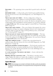
PREVIOUS ATTEMPTS AT BOOTING THIS SYSTEM HAVE FAILED AT CHECKPOINT [NNNN]. See your Service Manual at support.dell.com. See your Service Manual at support.dell.com). HA R D -DISK DRIVE FAILURE - KEYBOARD FAILURE - N O T I M E R T I C K I L U R E - A chip on page 65 for assistance). NOTICE - Troubleshooting 41 Replace battery. Replace processor fan. HA R D -D I S K D R I V E R E A D F A I N T E R R U P T - N O B O O T D E V I C A L S U P P O R T - USB OVER CURRENT ERROR - S.M.A.R.T error, possible...
PREVIOUS ATTEMPTS AT BOOTING THIS SYSTEM HAVE FAILED AT CHECKPOINT [NNNN]. See your Service Manual at support.dell.com. See your Service Manual at support.dell.com). HA R D -DISK DRIVE FAILURE - KEYBOARD FAILURE - N O T I M E R T I C K I L U R E - A chip on page 65 for assistance). NOTICE - Troubleshooting 41 Replace battery. Replace processor fan. HA R D -D I S K D R I V E R E A D F A I N T E R R U P T - N O B O O T D E V I C A L S U P P O R T - USB OVER CURRENT ERROR - S.M.A.R.T error, possible...
Quick Reference Guide
Page 45
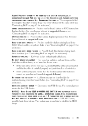
...keyboard, move the mouse, or press the power button to the same electrical outlet Troubleshooting 45 I F T H E P O W E R L I G H T I S B L I N K I S S T E A D Y A M B E R - I F T H E P O W E R L I G H T I N G A M B E R - There is a power problem, a device may be malfunctioning or incorrectly installed. • Remove and then reinstall all memory modules (see your Service Manual at support.dell...If the display is in standby mode. Some possible causes of interference are: • Power, keyboard, and mouse extension cables • Too many devices connected to the same power strip •...
...keyboard, move the mouse, or press the power button to the same electrical outlet Troubleshooting 45 I F T H E P O W E R L I G H T I S B L I N K I S S T E A D Y A M B E R - I F T H E P O W E R L I G H T I N G A M B E R - There is a power problem, a device may be malfunctioning or incorrectly installed. • Remove and then reinstall all memory modules (see your Service Manual at support.dell...If the display is in standby mode. Some possible causes of interference are: • Power, keyboard, and mouse extension cables • Too many devices connected to the same power strip •...
Quick Reference Guide
Page 47
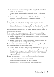
If necessary, uninstall and then reinstall the program. C H E C K T H E S O F T W A R E D O C U M E N T A T I O N - If you are unable to get a response by pressing a key on your keyboard or moving your mouse, press and hold the power button for an earlier Microsoft® Windows® operating system RUN THE PROGRAM COMPATIBILITY WIZARD - Windows ...
If necessary, uninstall and then reinstall the program. C H E C K T H E S O F T W A R E D O C U M E N T A T I O N - If you are unable to get a response by pressing a key on your keyboard or moving your mouse, press and hold the power button for an earlier Microsoft® Windows® operating system RUN THE PROGRAM COMPATIBILITY WIZARD - Windows ...
Quick Reference Guide
Page 48
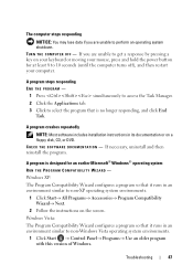
... are unable to get a response by pressing a key on the screen. 2 In the Welcome screen, click Next. 3 Follow the instructions on your keyboard or moving your mouse, press and hold the power button for at least 8 to check the hard drive, floppy disks, CDs, or DVDs •... Save and close any open files or programs and shut down your computer through the Start menu Dell Technical Update Service The Dell Technical Update service provides proactive e-mail notification of software and hardware updates for your computer. The service is installed and configured properly....
... are unable to get a response by pressing a key on the screen. 2 In the Welcome screen, click Next. 3 Follow the instructions on your keyboard or moving your mouse, press and hold the power button for at least 8 to check the hard drive, floppy disks, CDs, or DVDs •... Save and close any open files or programs and shut down your computer through the Start menu Dell Technical Update Service The Dell Technical Update service provides proactive e-mail notification of software and hardware updates for your computer. The service is installed and configured properly....

Quick Reference Guide
Page 57
... Windows System Restore to return your operating system to the operating state it was in the user name field, then click OK. 5 Click Dell Factory Image Restore. See "Using Microsoft® Windows® System Restore" on page 52. NOTE: Depending upon your configuration, you installed ...the new device driver. 3 In the System Recovery Options window, select a keyboard layout and click Next. 4 To access the recovery options, log on your primary hard drive. NOTICE: Before performing the installation, back up all data...
... Windows System Restore to return your operating system to the operating state it was in the user name field, then click OK. 5 Click Dell Factory Image Restore. See "Using Microsoft® Windows® System Restore" on page 52. NOTE: Depending upon your configuration, you installed ...the new device driver. 3 In the System Recovery Options window, select a keyboard layout and click Next. 4 To access the recovery options, log on your primary hard drive. NOTICE: Before performing the installation, back up all data...

Quick Reference Guide
Page 63
... your computer, follow the safety instructions in the documentation that the computer documentation is available. Getting Help 63 Remember to type some commands at the keyboard, relay detailed information during operations, or try other troubleshooting steps possible only at or near the computer. If possible, turn on page 64). CAUTION: Before...
... your computer, follow the safety instructions in the documentation that the computer documentation is available. Getting Help 63 Remember to type some commands at the keyboard, relay detailed information during operations, or try other troubleshooting steps possible only at or near the computer. If possible, turn on page 64). CAUTION: Before...
Service Manual
Page 1
... and/or other than its own. Bluetooth is strictly forbidden. Dell Inc. A02 is a registered trademark of Bluetooth SIG Inc. Model PP30L September 2009 Rev. Dell™ Latitude™ E6500 Service Manual Troubleshooting Before Working on Your Computer Base Assembly Hinge Covers... Hard Drive WLAN/WiMax Cards WWAN Card WPAN/UWB Cards Flash Cache Modules Fan Processor Thermal-Cooling Assembly Processor Module Memory Coin-Cell Battery Optical Drive LED Cover Keyboard...
... and/or other than its own. Bluetooth is strictly forbidden. Dell Inc. A02 is a registered trademark of Bluetooth SIG Inc. Model PP30L September 2009 Rev. Dell™ Latitude™ E6500 Service Manual Troubleshooting Before Working on Your Computer Base Assembly Hinge Covers... Hard Drive WLAN/WiMax Cards WWAN Card WPAN/UWB Cards Flash Cache Modules Fan Processor Thermal-Cooling Assembly Processor Module Memory Coin-Cell Battery Optical Drive LED Cover Keyboard...
Service Manual
Page 35
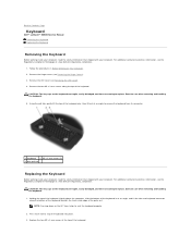
...to replace. Press each side to seat the keyboard properly. 2. Follow the procedures in at an angle, and fit the tabs and keyboard connector along the top of the keyboard only, then lift out at : www.dell.com/regulatory_compliance. 1. Using the pull tab, ... replace. Remove the hinge covers (see Removing the LED Cover). 4. Back to Contents Page Keyboard Dell™ Latitude™ E6500 Service Manual Removing the Keyboard Replacing the Keyboard Removing the Keyboard Before working inside your computer, read the safety information that shipped with your computer. Remove the...
...to replace. Press each side to seat the keyboard properly. 2. Follow the procedures in at an angle, and fit the tabs and keyboard connector along the top of the keyboard only, then lift out at : www.dell.com/regulatory_compliance. 1. Using the pull tab, ... replace. Remove the hinge covers (see Removing the LED Cover). 4. Back to Contents Page Keyboard Dell™ Latitude™ E6500 Service Manual Removing the Keyboard Replacing the Keyboard Removing the Keyboard Before working inside your computer, read the safety information that shipped with your computer. Remove the...

Service Manual
Page 36
Replace the hinge covers (see Replacing the Battery). Replace the dashboard panel from the top of the keyboard and carefully snap the panel. 5. Close the display and turn the computer over. 8. Replace the battery (see Replacing the Hinge Covers). 7. 1 M2 x 3-mm screws (2) 2 tabs (5) 3 keyboard connector 4. Back to Contents Page Replace the LED cover (see Replacing the LED Cover). 6.
Replace the hinge covers (see Replacing the Battery). Replace the dashboard panel from the top of the keyboard and carefully snap the panel. 5. Close the display and turn the computer over. 8. Replace the battery (see Replacing the Hinge Covers). 7. 1 M2 x 3-mm screws (2) 2 tabs (5) 3 keyboard connector 4. Back to Contents Page Replace the LED cover (see Replacing the LED Cover). 6.
Service Manual
Page 45
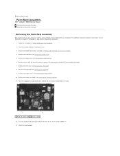
Back to Contents Page Palm Rest Assembly Dell™ Latitude™ E6500 Service Manual Removing the Palm Rest Assembly Replacing the Palm Rest Assembly Removing the Palm Rest Assembly Before working inside your computer. Follow the instructions ... the optical drive (see Removing the Display Assembly). 11. Lift off the thermal plate. Remove the bottom of the base assembly (see Removing the Keyboard). 9. Remove the keyboard (see Removing the Bottom of the Base Assembly). 4. Remove the fan with your computer, read the safety information that shipped with the thermal-cooling...
Back to Contents Page Palm Rest Assembly Dell™ Latitude™ E6500 Service Manual Removing the Palm Rest Assembly Replacing the Palm Rest Assembly Removing the Palm Rest Assembly Before working inside your computer. Follow the instructions ... the optical drive (see Removing the Display Assembly). 11. Lift off the thermal plate. Remove the bottom of the base assembly (see Removing the Keyboard). 9. Remove the keyboard (see Removing the Bottom of the Base Assembly). 4. Remove the fan with your computer, read the safety information that shipped with the thermal-cooling...
Service Manual
Page 47
... x 5-mm screws on the palm rest. 6. Replace the fan (see Replacing the Hinge Covers). 12. Turn the computer top-side up and replace the keyboard (see Replacing the Optical Drive). 9. Replace the four M2.5 x 5-mm screws, two on the silk-screen bar and two on the bottom of the ...Base Assembly). 13. Replace the optical drive (see Replacing the Keyboard). 10. Replace the battery (see Replacing the Display Assembly). 11. Replace the display assembly (see Replacing the Battery). Replace the bottom of the base ...
... x 5-mm screws on the palm rest. 6. Replace the fan (see Replacing the Hinge Covers). 12. Turn the computer top-side up and replace the keyboard (see Replacing the Optical Drive). 9. Replace the four M2.5 x 5-mm screws, two on the silk-screen bar and two on the bottom of the ...Base Assembly). 13. Replace the optical drive (see Replacing the Keyboard). 10. Replace the battery (see Replacing the Display Assembly). 11. Replace the display assembly (see Replacing the Battery). Replace the bottom of the base ...
Service Manual
Page 48
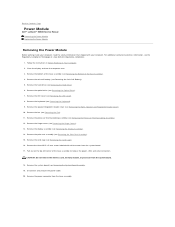
... the fan (see Removing the Coin-Cell Battery). 5. Pull out on Your Computer. 2. Remove the optical drive (see Removing the Keyboard). 9. Remove the keyboard (see Removing the Optical Drive). 7. CAUTION: Do not remove the wireless card, memory module, or processor from the base assembly. ... Follow the instructions in Before Working on the top left corner of the base assembly to Contents Page Power Module Dell™ Latitude™ E6500 Service Manual Removing the Power Module Replacing the Power Module Removing the Power Module Before working inside your computer, read...
... the fan (see Removing the Coin-Cell Battery). 5. Pull out on Your Computer. 2. Remove the optical drive (see Removing the Keyboard). 9. Remove the keyboard (see Removing the Optical Drive). 7. CAUTION: Do not remove the wireless card, memory module, or processor from the base assembly. ... Follow the instructions in Before Working on the top left corner of the base assembly to Contents Page Power Module Dell™ Latitude™ E6500 Service Manual Removing the Power Module Replacing the Power Module Removing the Power Module Before working inside your computer, read...


