
Outline Drawing
Page 1
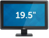
E2014T Outline Dimension 55.0 (2.16) 13.4 (0.53) 16.5 (0.65) 311.2 (12.25) 278.2 (10.95) 16.5 (0.65) 505.9 (19.91) 472.9 (18.62) 180.0 (7.09) 64.8 (2.55) 376.0 (14.80) 370.2 (14.57) 1.0 (0.04) 45.0 (1.77) 51.7 (2.03) 100.0 2X (3.94) Z = 0 122.0 2X (4.80) Z = 42.8 (1.69) Z = 43.8 (1.72) Nominal Dimensions Unit:mm(inch) 2.2 (0.09) Back view of Monitor without stand Tilt 5.5° 31° 155.7 (6.13) 384.6 (15.14) 289.8 (11.41) 15.4 (0.61) 203.2 (8.00) 64.7 (2.55) 38.7 (15.24) 165.0 (6.50)
E2014T Outline Dimension 55.0 (2.16) 13.4 (0.53) 16.5 (0.65) 311.2 (12.25) 278.2 (10.95) 16.5 (0.65) 505.9 (19.91) 472.9 (18.62) 180.0 (7.09) 64.8 (2.55) 376.0 (14.80) 370.2 (14.57) 1.0 (0.04) 45.0 (1.77) 51.7 (2.03) 100.0 2X (3.94) Z = 0 122.0 2X (4.80) Z = 42.8 (1.69) Z = 43.8 (1.72) Nominal Dimensions Unit:mm(inch) 2.2 (0.09) Back view of Monitor without stand Tilt 5.5° 31° 155.7 (6.13) 384.6 (15.14) 289.8 (11.41) 15.4 (0.61) 203.2 (8.00) 64.7 (2.55) 38.7 (15.24) 165.0 (6.50)
Setup Diagram
Page 1
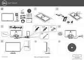
.... A00 P/N 90.7AC39.011 July 2013 Made in China ©2013 Dell Inc. E2014T Drivers and Documentation Dell™ E2014T Flat Panel Monitor Contents: • Device drivers • Quick Setup Guide • User's Guide • Dell Display Manager Software P/N VDPTM Rev. All 46.7AC03.001 (DELL P/N:DY3YP rev.A00) All DP HDMI VGA USB 5.5° 31°...
.... A00 P/N 90.7AC39.011 July 2013 Made in China ©2013 Dell Inc. E2014T Drivers and Documentation Dell™ E2014T Flat Panel Monitor Contents: • Device drivers • Quick Setup Guide • User's Guide • Dell Display Manager Software P/N VDPTM Rev. All 46.7AC03.001 (DELL P/N:DY3YP rev.A00) All DP HDMI VGA USB 5.5° 31°...
Users Guide
Page 3
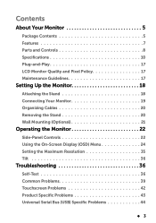
... and Controls 8 Specifications 10 Plug-and-Play 17 LCD Monitor Quality and Pixel Policy 17 Maintenance Guidelines 17 Setting Up the Monitor 18 Attaching the Stand 18 Connecting Your Monitor 19 Organizing Cables 20 Removing the Stand 20 Wall Mounting (Optional 21 Operating the Monitor 22 Side-Panel Controls 22 Using the On-Screen...
... and Controls 8 Specifications 10 Plug-and-Play 17 LCD Monitor Quality and Pixel Policy 17 Maintenance Guidelines 17 Setting Up the Monitor 18 Attaching the Stand 18 Connecting Your Monitor 19 Organizing Cables 20 Removing the Stand 20 Wall Mounting (Optional 21 Operating the Monitor 22 Side-Panel Controls 22 Using the On-Screen...

Users Guide
Page 4
Appendix 45 Safety Instructions 45 FCC Notices (U.S. only) and Other Regulatory Information . . 45 Contacting Dell 45 Setting Display Resolution to 1600 x 900 (maximum 46 Downloading Latest Video Drivers 46 Setting up Dual Monitors 47 Display Styles For Multiple Monitors 52 4 About Your Monitor
Appendix 45 Safety Instructions 45 FCC Notices (U.S. only) and Other Regulatory Information . . 45 Contacting Dell 45 Setting Display Resolution to 1600 x 900 (maximum 46 Downloading Latest Video Drivers 46 Setting up Dual Monitors 47 Display Styles For Multiple Monitors 52 4 About Your Monitor

Users Guide
Page 5
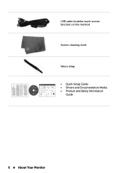
Monitor Stand Power cable (varies by country) HDMI cable About Your Monitor 5 NOTE: To set up with the components shown below. NOTE: Some items may be optional and may not be available in certain countries. About Your Monitor Package Contents Your monitor ships with any other stand, see the documentation for the stand. Make sure that you have received all the components and contact Dell if something is missing. Some features or media may not ship with your monitor.
Monitor Stand Power cable (varies by country) HDMI cable About Your Monitor 5 NOTE: To set up with the components shown below. NOTE: Some items may be optional and may not be available in certain countries. About Your Monitor Package Contents Your monitor ships with any other stand, see the documentation for the stand. Make sure that you have received all the components and contact Dell if something is missing. Some features or media may not ship with your monitor.
Users Guide
Page 6
USB cable (enables touch screen function on the monitor) Screen cleaning cloth Velcro strap • Quick Setup Guide • Drivers and Documentation Media • Product and Safety Information Guide 6 About Your Monitor
USB cable (enables touch screen function on the monitor) Screen cleaning cloth Velcro strap • Quick Setup Guide • Drivers and Documentation Media • Product and Safety Information Guide 6 About Your Monitor

Users Guide
Page 7
... and screen optimization. • Security cable slot. • Stand lock. • INF file, Image and color matching (ICM) file, Dell Display Manager software, and product documentation included in the media shipped with your monitor. • Asset management capability. • Energy Star compliant. • EPEAT Gold compliant. • BFR/PVC-reduced. • Arsenic...
... and screen optimization. • Security cable slot. • Stand lock. • INF file, Image and color matching (ICM) file, Dell Display Manager software, and product documentation included in the media shipped with your monitor. • Asset management capability. • Energy Star compliant. • EPEAT Gold compliant. • BFR/PVC-reduced. • Arsenic...

Users Guide
Page 8
Stand release button Releases the stand from the monitor. 8 About Your Monitor Regulatory label Lists the regulatory approvals. Parts and Controls Front View ew Side-panel controls Label 1 2 Description Function buttons (For more information, see Operating the Monitor) Power On/Off button (with indicator light) Back View Label 1 2 3 Description Use 100 mm x 100 mm Wall mount monitor using VESA mounting holes 100 mm x 100 mm VESA-compatible (under VESA cover) wall-mount kit.
Stand release button Releases the stand from the monitor. 8 About Your Monitor Regulatory label Lists the regulatory approvals. Parts and Controls Front View ew Side-panel controls Label 1 2 Description Function buttons (For more information, see Operating the Monitor) Power On/Off button (with indicator light) Back View Label 1 2 3 Description Use 100 mm x 100 mm Wall mount monitor using VESA mounting holes 100 mm x 100 mm VESA-compatible (under VESA cover) wall-mount kit.

Users Guide
Page 9
... Use a M3 x 6 mm screw to lock the stand to contact Dell for technical support. 5 Dell soundbar mounting slots Attaches the Dell Soundbar (optional). 6 Cable management Organize cables by placing them through the slot. 4 Barcode serial number label Refer to this label if you need to the monitor. (screw not included) Connect the power cable.
... Use a M3 x 6 mm screw to lock the stand to contact Dell for technical support. 5 Dell soundbar mounting slots Attaches the Dell Soundbar (optional). 6 Cable management Organize cables by placing them through the slot. 4 Barcode serial number label Refer to this label if you need to the monitor. (screw not included) Connect the power cable.
Users Guide
Page 10
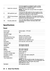
...3H 3~5 gloss units >30 gloss units NOTE: The user should consider the placement of the display as the reflection of the monitor. (security cable sold separately) Specifications Panel Screen type Panel type Viewable image Diagonal Horizontal Active Area Vertical Active Area Area Pixel ...pitch Viewing angle Horizontal Vertical Luminance Panel Monitor Contrast ratio Dynamic contrast ratio Faceplate coating Bezel gloss Touch glass gloss Backlight Active matrix - NOTE: The audio line-out port...
...3H 3~5 gloss units >30 gloss units NOTE: The user should consider the placement of the display as the reflection of the monitor. (security cable sold separately) Specifications Panel Screen type Panel type Viewable image Diagonal Horizontal Active Area Vertical Active Area Area Pixel ...pitch Viewing angle Horizontal Vertical Luminance Panel Monitor Contrast ratio Dynamic contrast ratio Faceplate coating Bezel gloss Touch glass gloss Backlight Active matrix - NOTE: The audio line-out port...

Users Guide
Page 11
...and vertical synchronizations. • Polarity-free TTL level • SOG (composite SYNC on green) 100 VAC to wake up the monitor. Touch Type Panel diagonal Panel thickness Active area Cover glass thickness Input method Touch point Output position resolution Touch method Operating system ...beyond viewing area 3.0 +0.0/-0.3 mm Bare finger, thin gloves, conductive stylus 5 touch-points 32767 x 32767 Fingers and thin gloves Windows 8 certified NOTE: When the monitor is based on the screen to 240 VAC Frequency 50 Hz or 60 Hz + 3 Hz Current 1.5 A (Max.) Inrush current 120 V:70 A (Max.)...
...and vertical synchronizations. • Polarity-free TTL level • SOG (composite SYNC on green) 100 VAC to wake up the monitor. Touch Type Panel diagonal Panel thickness Active area Cover glass thickness Input method Touch point Output position resolution Touch method Operating system ...beyond viewing area 3.0 +0.0/-0.3 mm Bare finger, thin gloves, conductive stylus 5 touch-points 32767 x 32767 Fingers and thin gloves Windows 8 certified NOTE: When the monitor is based on the screen to 240 VAC Frequency 50 Hz or 60 Hz + 3 Hz Current 1.5 A (Max.) Inrush current 120 V:70 A (Max.)...

Users Guide
Page 12
... DisplayPort 1.2 port Maximum resolution: 1600 x 900 Two HDMI/MHL ports Maximum resolution: 1600 x 900 One VGA port Maximum resolution: 1600 x 900 12 About Your Monitor
... DisplayPort 1.2 port Maximum resolution: 1600 x 900 Two HDMI/MHL ports Maximum resolution: 1600 x 900 One VGA port Maximum resolution: 1600 x 900 12 About Your Monitor

Users Guide
Page 13
This is referred to as Power Save Mode. no cables) Weight of Power Save Mode: About Your Monitor 13 USB Audio Signal cable type Dimensions (with stand) Height Width Depth Dimensions (without stand) Height Width Depth Stand dimensions Height ...Weight without stand assembly (For wall mount or VESA mount considerations - If the computer detects input from keyboard, mouse, or other input devices, the monitor automatically resumes functioning. The following table shows the power consumption and signaling of stand assembly One USB 2.0 upstream port Two USB 2.0 downstream ports One...
This is referred to as Power Save Mode. no cables) Weight of Power Save Mode: About Your Monitor 13 USB Audio Signal cable type Dimensions (with stand) Height Width Depth Dimensions (without stand) Height Width Depth Stand dimensions Height ...Weight without stand assembly (For wall mount or VESA mount considerations - If the computer detects input from keyboard, mouse, or other input devices, the monitor automatically resumes functioning. The following table shows the power consumption and signaling of stand assembly One USB 2.0 upstream port Two USB 2.0 downstream ports One...

Users Guide
Page 14
... functions only in OFF mode can only be achieved by disconnecting the power cable from the monitor. Power Indicator White Brething white Off Power Consumption 16 W (typical) 40 W (maximum) Less than 0.5 W Less than 0.5 W NOTE: This monitor is pressed in Active-off Horizontal Vertical Sync Sync Active Active Inactive Inactive - - Video Active ...consumption in the normal operation mode. VESA Modes Normal operation Active-off mode Switch off mode, the following message is displayed: 14 About Your Monitor If you press any button is ENERGY STAR®-compliant.
... functions only in OFF mode can only be achieved by disconnecting the power cable from the monitor. Power Indicator White Brething white Off Power Consumption 16 W (typical) 40 W (maximum) Less than 0.5 W Less than 0.5 W NOTE: This monitor is pressed in Active-off Horizontal Vertical Sync Sync Active Active Inactive Inactive - - Video Active ...consumption in the normal operation mode. VESA Modes Normal operation Active-off mode Switch off mode, the following message is displayed: 14 About Your Monitor If you press any button is ENERGY STAR®-compliant.

Users Guide
Page 15
TMDS Clock Pin Number 11 12 13 14 15 16 17 18 19 19-pin Side of the monitor connector TMDS Data 2+ TMDS Data 2 Shield TMDS Data 2- TMDS Data 1+ TMDS Data 1 Shield TMDS Data 1TMDS Data 0+ TMDS Data 0 Shield TMDS Data 0- Pin Assignments VGA ...-pin Side of the Connected Signal Cable Computer 5 V/3.3 V GND-sync GND DDC data H-sync V-sync DDC clock Pin Number 1 2 3 4 5 6 7 8 9 10 19-pin Side of the monitor connector TMDS Clock Shield TMDS ClockFloating Floating DDC Clock (SDA) DDC Data (SDA) Ground +5 V Power Hot plug detect About Your...
TMDS Clock Pin Number 11 12 13 14 15 16 17 18 19 19-pin Side of the monitor connector TMDS Data 2+ TMDS Data 2 Shield TMDS Data 2- TMDS Data 1+ TMDS Data 1 Shield TMDS Data 1TMDS Data 0+ TMDS Data 0 Shield TMDS Data 0- Pin Assignments VGA ...-pin Side of the Connected Signal Cable Computer 5 V/3.3 V GND-sync GND DDC data H-sync V-sync DDC clock Pin Number 1 2 3 4 5 6 7 8 9 10 19-pin Side of the monitor connector TMDS Clock Shield TMDS ClockFloating Floating DDC Clock (SDA) DDC Data (SDA) Ground +5 V Power Hot plug detect About Your...

Users Guide
Page 16
... computer has the following USB ports: • 1 upstream • 2 downstream NOTE: The USB ports on your monitor. DisplayPort Pin Number 20-pin Side of the monitor connector Pin Number 20-pin Side of the monitor connector 1 ML0 (p) 11 GND 2 GND 12 ML3 (n) 3 ML0 (n) 13 GND 4 ML1 (p) 14 GND 5 GND 15 AUX (p) 6 ML1 (n) 16... HPD 9 ML2 (n) 19 DP_PWR Return 10 ML3 (p) 20 +3.3 V DP_PWR Universal Serial Bus (USB) This section gives you information about the USB ports available on this monitor are USB 2.0 compliant.
... computer has the following USB ports: • 1 upstream • 2 downstream NOTE: The USB ports on your monitor. DisplayPort Pin Number 20-pin Side of the monitor connector Pin Number 20-pin Side of the monitor connector 1 ML0 (p) 11 GND 2 GND 12 ML3 (n) 3 ML0 (n) 13 GND 4 ML1 (p) 14 GND 5 GND 15 AUX (p) 6 ML1 (n) 16... HPD 9 ML2 (n) 19 DP_PWR Return 10 ML3 (p) 20 +3.3 V DP_PWR Universal Serial Bus (USB) This section gives you information about the USB ports available on this monitor are USB 2.0 compliant.
Users Guide
Page 17
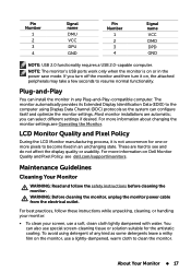
For more information on , the attached peripherals may take a few seconds to resume normal functionality. LCD Monitor Quality and Pixel Policy During the LCD Monitor manufacturing process, it on Dell Monitor Quality and Pixel Policy, see dell.com/support/monitors. Pin Number 1 2 3 4 Signal name DMU VCC DPU GND Pin Number 1 2 3 4 Signal name VCC DMD DPD GND NOTE...
For more information on , the attached peripherals may take a few seconds to resume normal functionality. LCD Monitor Quality and Pixel Policy During the LCD Monitor manufacturing process, it on Dell Monitor Quality and Pixel Policy, see dell.com/support/monitors. Pin Number 1 2 3 4 Signal name DMU VCC DPU GND Pin Number 1 2 3 4 Signal name VCC DMD DPD GND NOTE...

Users Guide
Page 18
... purchased a different stand for your monitor when not in the back of the monitor. 3. Setting Up the Monitor Attaching the Stand NOTE: The stand is shipped from monitor when it snaps into its place. 18 Setting Up the Monitor To attach the monitor stand: 1. CAUTION: Do not...surface. 2. NOTE: If you unpack your monitor, wipe it off with a soft and clean cloth. • Handle your monitor with care to clean the monitor. Place the monitor on your monitor, use a dynamically changing screen saver and turn off your monitor, see the documentation for that stand for setup...
... purchased a different stand for your monitor when not in the back of the monitor. 3. Setting Up the Monitor Attaching the Stand NOTE: The stand is shipped from monitor when it snaps into its place. 18 Setting Up the Monitor To attach the monitor stand: 1. CAUTION: Do not...surface. 2. NOTE: If you unpack your monitor, wipe it off with a soft and clean cloth. • Handle your monitor with care to clean the monitor. Place the monitor on your monitor, use a dynamically changing screen saver and turn off your monitor, see the documentation for that stand for setup...

Users Guide
Page 19
Connecting Your Monitor WARNING: Follow the Safety Instructions before you perform any of the following display cables to your computer: VGA cable, DisplayPort cable, or HDMI cable NOTE: Do not connect multiple display cables to the computer: 1. Turn off your monitor to the same computer. Connecting the VGA Cable Connecting the DisplayPort Cable Connecting the HDMI Cable Setting Up the Monitor 19 Connect the USB cable and only one of the procedures in this section, To connect your computer and disconnect the power cable from the wall outlet. 2.
Connecting Your Monitor WARNING: Follow the Safety Instructions before you perform any of the following display cables to your computer: VGA cable, DisplayPort cable, or HDMI cable NOTE: Do not connect multiple display cables to the computer: 1. Turn off your monitor to the same computer. Connecting the VGA Cable Connecting the DisplayPort Cable Connecting the HDMI Cable Setting Up the Monitor 19 Connect the USB cable and only one of the procedures in this section, To connect your computer and disconnect the power cable from the wall outlet. 2.

Users Guide
Page 20
Removing the Stand NOTE: To avoid scratching on a clean surface. NOTE: If you connect all necessary cables to organize the cables. Organizing Cables After you purchased a different stand for your monitor and computer, use the cable-management slot to your monitor, see the documentation for that the monitor is placed on the LCD screen while removing the stand, make sure that stand for the purpose of the computer may vary. Connecting the USB Cable NOTE: The graphics are used for setup instructions. 20 Setting Up the Monitor Appearance of illustration only.
Removing the Stand NOTE: To avoid scratching on a clean surface. NOTE: If you connect all necessary cables to organize the cables. Organizing Cables After you purchased a different stand for your monitor and computer, use the cable-management slot to your monitor, see the documentation for that the monitor is placed on the LCD screen while removing the stand, make sure that stand for the purpose of the computer may vary. Connecting the USB Cable NOTE: The graphics are used for setup instructions. 20 Setting Up the Monitor Appearance of illustration only.


