
User Guide
Page 1
DSS-24 Auto Negotiation Switch User's Guide Rev. 02 (Oct, 2004) 651DS24..K15 i
DSS-24 Auto Negotiation Switch User's Guide Rev. 02 (Oct, 2004) 651DS24..K15 i

User Guide
Page 3
... product. All other trademarks belong to Part 15 of the FCC Rules. In a domestic environment, this user's guide, may be revised without permission from D-Link Corporation/D-Link Systems Inc., as translation, transformation, or adaptation without prior notice. Tel. (44)181-203-9900 Fax.... Pao Chiao Road, Hsin Tien Taipei, Taiwan TEL. (886)2-916-1600 Trademarks Copyright ©1999 D-Link Corporation. Operation of D-Link Corporation/D-Link Systems, Inc. iii FlexSWITCHTM is a registered trademark of this publication may be required to correct the interference...
... product. All other trademarks belong to Part 15 of the FCC Rules. In a domestic environment, this user's guide, may be revised without permission from D-Link Corporation/D-Link Systems Inc., as translation, transformation, or adaptation without prior notice. Tel. (44)181-203-9900 Fax.... Pao Chiao Road, Hsin Tien Taipei, Taiwan TEL. (886)2-916-1600 Trademarks Copyright ©1999 D-Link Corporation. Operation of D-Link Corporation/D-Link Systems, Inc. iii FlexSWITCHTM is a registered trademark of this publication may be required to correct the interference...
User Guide
Page 7
... in general. All the information you need to other D-Link products is installing the DSS-24 on the DSS-24. Chapter 2, Installing the DSS-24, covers installing and powering on a network. Chapter 3, Connecting the DSS-24 to the DSS-24 10/100 Auto Negotiation Switch as the DSS-24. DSS-24 10/100 Auto Negotiation Switch User's Guide About This Guide This section defines the scope of this manual will...
... in general. All the information you need to other D-Link products is installing the DSS-24 on the DSS-24. Chapter 2, Installing the DSS-24, covers installing and powering on a network. Chapter 3, Connecting the DSS-24 to the DSS-24 10/100 Auto Negotiation Switch as the DSS-24. DSS-24 10/100 Auto Negotiation Switch User's Guide About This Guide This section defines the scope of this manual will...
User Guide
Page 8
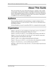
... section describes the features of the DSS-24. DSS-24 10/100 Auto Negotiation Switch User's Guide 1 Introduction This chapter gives a physical and functional overview of the DSS-24. Many of Front and Rear Panels • Management Features The DSS-24 has the following features: • 24 NWAY 10/100-TX Fast Ethernet ...will be used in the manual. The DSS-24 can be dealt with in more detail later in conjunction with polarity detection and correcting. • Wire speed packet filtering and forwarding. • Per port LED to indicate link, activity, speed and operation modes. ...
... section describes the features of the DSS-24. DSS-24 10/100 Auto Negotiation Switch User's Guide 1 Introduction This chapter gives a physical and functional overview of the DSS-24. Many of Front and Rear Panels • Management Features The DSS-24 has the following features: • 24 NWAY 10/100-TX Fast Ethernet ...will be used in the manual. The DSS-24 can be dealt with in more detail later in conjunction with polarity detection and correcting. • Wire speed packet filtering and forwarding. • Per port LED to indicate link, activity, speed and operation modes. ...
User Guide
Page 9
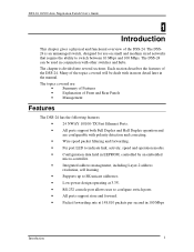
... Fast Ethernet Switch Switch II Link/ 100 Mbps/ Collision 10 Mbps 1 234 56 7 9 10 11 12 Link/ 100 Mbps/ D-Link Collision 10 Mbps 13 14 15 17 18 19 21 22 23 17x 18x 19x 20x 21x 22x 23x 24x 100Mbps/10Mbps Figure 1: DSS-24 Front Panel Introduction 3 DSS-24 10/100 Auto Negotiation Switch User's Guide Front Panel The DSS-24 is designed...
... Fast Ethernet Switch Switch II Link/ 100 Mbps/ Collision 10 Mbps 1 234 56 7 9 10 11 12 Link/ 100 Mbps/ D-Link Collision 10 Mbps 13 14 15 17 18 19 21 22 23 17x 18x 19x 20x 21x 22x 23x 24x 100Mbps/10Mbps Figure 1: DSS-24 Front Panel Introduction 3 DSS-24 10/100 Auto Negotiation Switch User's Guide Front Panel The DSS-24 is designed...
User Guide
Page 10
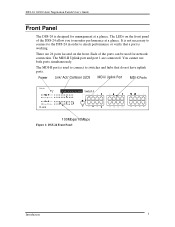
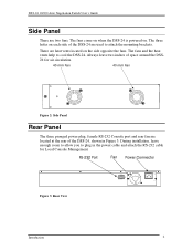
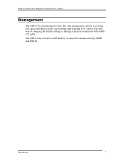
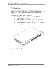
... heat vents located on . The fans and the heat vents help to attach the mounting brackets. DSS-24 10/100 Auto Negotiation Switch User's Guide Side Panel There are located at the rear of the DSS-24, shown in the power cable and attach the RS-232 cable for air circulation. 40 mm Fan 40 mm Fan... port and rear fan are two fans. During installation, leave enough room to allow you to plug in Figure 3. There are used to cool the DSS-24. RS-232 Port Fan Power Connector Figure 3: Rear View Introduction 4 The fans come on when the...
... heat vents located on . The fans and the heat vents help to attach the mounting brackets. DSS-24 10/100 Auto Negotiation Switch User's Guide Side Panel There are located at the rear of the DSS-24, shown in the power cable and attach the RS-232 cable for air circulation. 40 mm Fan 40 mm Fan... port and rear fan are two fans. During installation, leave enough room to allow you to plug in Figure 3. There are used to cool the DSS-24. RS-232 Port Fan Power Connector Figure 3: Rear View Introduction 4 The fans come on when the...
User Guide
Page 11
The only management options are setting port speed and duplex mode, and enabling and disabling flow control. Introduction 5 It can not be monitored using SNMP and RMON. The only way of changing the default settings is an unmanaged switch. The DSS-24 does not have an IP address. DSS-24 10/100 Auto Negotiation Switch User's Guide Management The DSS-24 is through a physical connection with an RS232 cable.
The only management options are setting port speed and duplex mode, and enabling and disabling flow control. Introduction 5 It can not be monitored using SNMP and RMON. The only way of changing the default settings is an unmanaged switch. The DSS-24 does not have an IP address. DSS-24 10/100 Auto Negotiation Switch User's Guide Management The DSS-24 is through a physical connection with an RS232 cable.
User Guide
Page 12
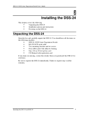
... all the items on the DSS-24 Unpacking the DSS-24 Open the box and carefully unpack the DSS-24. Be sure to register may void the warranty. Installing the DSS-16 and DSS-24 6 Failure to register the DSS-24 immediately. DSS-24 10/100 Auto Negotiation Switch User's Guide 2 Installing the DSS-24 This chapter covers the following: • Unpacking the DSS-24 • Installation options and instructions...
... all the items on the DSS-24 Unpacking the DSS-24 Open the box and carefully unpack the DSS-24. Be sure to register may void the warranty. Installing the DSS-16 and DSS-24 6 Failure to register the DSS-24 immediately. DSS-24 10/100 Auto Negotiation Switch User's Guide 2 Installing the DSS-24 This chapter covers the following: • Unpacking the DSS-24 • Installation options and instructions...
User Guide
Page 13
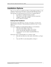
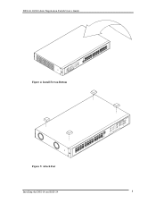
...-45 connectors as needed for installing the DSS-24: desktop/shelf installation or rack installation. Place the DSS-24 on a desktop or shelf: 1. The procedures for each are two options for network connections. • Crimpers to install the DSS-24 on the desktop/shelf, see Figure 4. 2. DSS-24 10/100 Auto Negotiation Switch User's Guide Installation Options There are explained in...
...-45 connectors as needed for installing the DSS-24: desktop/shelf installation or rack installation. Place the DSS-24 on a desktop or shelf: 1. The procedures for each are two options for network connections. • Crimpers to install the DSS-24 on the desktop/shelf, see Figure 4. 2. DSS-24 10/100 Auto Negotiation Switch User's Guide Installation Options There are explained in...
User Guide
Page 14
DSS-24 10/100 Auto Negotiation Switch User's Guide Figure 4: Install Feet on Bottom Figure 5: Attach Feet Installing the DSS-16 and DSS-24 8
DSS-24 10/100 Auto Negotiation Switch User's Guide Figure 4: Install Feet on Bottom Figure 5: Attach Feet Installing the DSS-16 and DSS-24 8
User Guide
Page 15
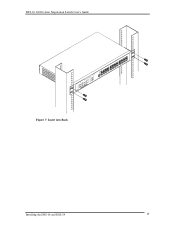
... in an EIA standard size 19 inch rack. Slide the DSS-24 into the rack and use the screws provided to secure the DSS-24 to the rack, see Figure 6. 2. Figure 6: Attach Mounting Brackets Installing the DSS-16 and DSS-24 9 DSS-24 10/100 Auto Negotiation Switch User's Guide Rack Installation The DSS-24 can be mounted in a wiring closet along with the...
... in an EIA standard size 19 inch rack. Slide the DSS-24 into the rack and use the screws provided to secure the DSS-24 to the rack, see Figure 6. 2. Figure 6: Attach Mounting Brackets Installing the DSS-16 and DSS-24 9 DSS-24 10/100 Auto Negotiation Switch User's Guide Rack Installation The DSS-24 can be mounted in a wiring closet along with the...
User Guide
Page 16
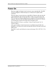
DSS-24 10/100 Auto Negotiation Switch User's Guide Figure 7: Insert into Rack Installing the DSS-16 and DSS-24 10
DSS-24 10/100 Auto Negotiation Switch User's Guide Figure 7: Insert into Rack Installing the DSS-16 and DSS-24 10
User Guide
Page 17
... no on when you plug the power cord into the three pronged power connector. Contact D-Link Systems, Inc. for technical support. The DSS-24 can be plugged in the range 100 to 240 VAC., 50 to 60 Hz. The DSS24 may be necessary to the local power source ... the DSS-16 and DSS-24 11 The DSS-24 powers on /off switch. Reboot the DSS-24 if there is located at the rear of the DSS-24. The power plug is a problem. After a power failure, it may be used with power sources in without having any ports that were manually set. DSS-24 10/100 Auto Negotiation Switch User's Guide Power On...
... no on when you plug the power cord into the three pronged power connector. Contact D-Link Systems, Inc. for technical support. The DSS-24 can be plugged in the range 100 to 240 VAC., 50 to 60 Hz. The DSS24 may be necessary to the local power source ... the DSS-16 and DSS-24 11 The DSS-24 powers on /off switch. Reboot the DSS-24 if there is located at the rear of the DSS-24. The power plug is a problem. After a power failure, it may be used with power sources in without having any ports that were manually set. DSS-24 10/100 Auto Negotiation Switch User's Guide Power On...
User Guide
Page 18
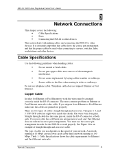
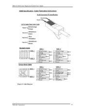
... has eight wires inside the RJ-45 connector. You must be used when connecting to servers, switches, hubs, workstations and other devices. Network Connections 12 DSS-24 10/100 Auto Negotiation Switch User's Guide 3 Network Connections This chapter covers the following guidelines when handling cables: • Do not stretch... you use the correct pin arrangement in aisles or walkways. Straight through and crossover cable. See Figure 8 for the DSS-24 to work the wires must use depends on Ethernet or Fast Ethernet networks is extremely important that cables have the correct pin...
... has eight wires inside the RJ-45 connector. You must be used when connecting to servers, switches, hubs, workstations and other devices. Network Connections 12 DSS-24 10/100 Auto Negotiation Switch User's Guide 3 Network Connections This chapter covers the following guidelines when handling cables: • Do not stretch... you use the correct pin arrangement in aisles or walkways. Straight through and crossover cable. See Figure 8 for the DSS-24 to work the wires must use depends on Ethernet or Fast Ethernet networks is extremely important that cables have the correct pin...
User Guide
Page 19
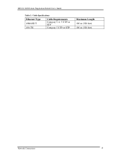
DSS-24 10/100 Auto Negotiation Switch User's Guide Table 1: Cable Specifications Ethernet Type 10BASE-T 100-TX Cable Requirements Category 3, 4, 5 UTP or STP Category 5 UTP or STP Maximum Length 100 m (328 feet) 100 m (328 feet) Network Connections 13
DSS-24 10/100 Auto Negotiation Switch User's Guide Table 1: Cable Specifications Ethernet Type 10BASE-T 100-TX Cable Requirements Category 3, 4, 5 UTP or STP Category 5 UTP or STP Maximum Length 100 m (328 feet) 100 m (328 feet) Network Connections 13
User Guide
Page 20
DSS-24 10/100 Auto Negotiation Switch User's Guide Figure 8: Cable Diagram Network Connections 14
DSS-24 10/100 Auto Negotiation Switch User's Guide Figure 8: Cable Diagram Network Connections 14
User Guide
Page 21
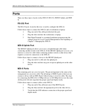
... are the same. Network Connections 15 Plug one end of MDI-X ports is used to connect the DSS-24 and a workstation or laptop: 1. DSS-24 10/100 Auto Negotiation Switch User's Guide Ports There are three types of Chapter 5, Managing the DSS-24. RS-232 Port The RS-232 port, located at the rear, is that you to use...
... are the same. Network Connections 15 Plug one end of MDI-X ports is used to connect the DSS-24 and a workstation or laptop: 1. DSS-24 10/100 Auto Negotiation Switch User's Guide Ports There are three types of Chapter 5, Managing the DSS-24. RS-232 Port The RS-232 port, located at the rear, is that you to use...
User Guide
Page 22
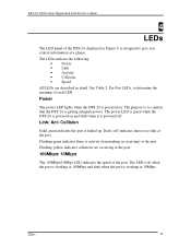
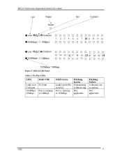
...) at the port. The purpose is to confirm that the DSS-24 is linked up. Flashing yellow indicates collisions are described in Figure 9, is no link at the port. LEDs 16 Power The power LED lights when the DSS-24 is powered on and dark when it is powered off ) ... is designed to determine the meaning of each LED. Link/ Act/ Collision Solid green indicates the port is getting adequate power. See Table 2: Per Port LEDs, to give you critical information at a glance. DSS-24 10/100 Auto Negotiation Switch User's Guide 4 LEDs The LED panel of the DSS-24, displayed in detail.
...) at the port. The purpose is to confirm that the DSS-24 is linked up. Flashing yellow indicates collisions are described in Figure 9, is no link at the port. LEDs 16 Power The power LED lights when the DSS-24 is powered on and dark when it is powered off ) ... is designed to determine the meaning of each LED. Link/ Act/ Collision Solid green indicates the port is getting adequate power. See Table 2: Per Port LEDs, to give you critical information at a glance. DSS-24 10/100 Auto Negotiation Switch User's Guide 4 LEDs The LED panel of the DSS-24, displayed in detail.
User Guide
Page 23
DSS-24 10/100 Auto Negotiation Switch User's Guide Link Power Power Act Collision Link/ 100Mbps/ Collision 10Mbps 1 234 56 7 9 10 11 12 Link/ 100Mbps/ Collision 10Mbps 13 14 15 17 18 19 21 22 23 100Mbps/ 10Mbps Figure 9: DSS-24 LED Panel Table 2: Per Port LEDs LED Dark (Off) Link/ Act/ Collision 100Mbps/ 10Mbps No Link Port is running at 10Mbps Solid Green Link Up but No Activity Port is running at 100Mbps Flashing Green Transmitting or Receiving Not applicable Flashing Yellow Collisions are occurring Not applicable LEDs 17
DSS-24 10/100 Auto Negotiation Switch User's Guide Link Power Power Act Collision Link/ 100Mbps/ Collision 10Mbps 1 234 56 7 9 10 11 12 Link/ 100Mbps/ Collision 10Mbps 13 14 15 17 18 19 21 22 23 100Mbps/ 10Mbps Figure 9: DSS-24 LED Panel Table 2: Per Port LEDs LED Dark (Off) Link/ Act/ Collision 100Mbps/ 10Mbps No Link Port is running at 10Mbps Solid Green Link Up but No Activity Port is running at 100Mbps Flashing Green Transmitting or Receiving Not applicable Flashing Yellow Collisions are occurring Not applicable LEDs 17
User Guide
Page 24
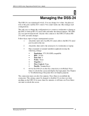
... laptop to the DSS-24 with an RS232 cable can change the configuration is established. DSS-24 10/100 Auto Negotiation Switch User's Guide 5 Managing the DSS-24 The DSS-24 is not password protected. Anyone who connects to the DSS-24 with an RS-232...only way to the RS-232 serial port located at the rear. 2. The DSS24 is an unmanaged switch. Follow these steps to reestablish the connection. You cannot make changes. Attach the other changes and ...Press Enter to refresh the screen. Power the DSS-24 on the DSS-24 for more than five minutes, it will time out.
... laptop to the DSS-24 with an RS232 cable can change the configuration is established. DSS-24 10/100 Auto Negotiation Switch User's Guide 5 Managing the DSS-24 The DSS-24 is not password protected. Anyone who connects to the DSS-24 with an RS-232...only way to the RS-232 serial port located at the rear. 2. The DSS24 is an unmanaged switch. Follow these steps to reestablish the connection. You cannot make changes. Attach the other changes and ...Press Enter to refresh the screen. Power the DSS-24 on the DSS-24 for more than five minutes, it will time out.

