User Guide
Page 2
... card, provided at the back of this manual, must be prominently marked on which may be free from date of such repair, irrespective of the package. A list of the Registration Card. Warranty service may otherwise be provided. D-Link makes no obligation to mailing or shipping costs. D-Link Limited Warranty Hardware: D-Link warrants its software product, against failure during the same...
... card, provided at the back of this manual, must be prominently marked on which may be free from date of such repair, irrespective of the package. A list of the Registration Card. Warranty service may otherwise be provided. D-Link makes no obligation to mailing or shipping costs. D-Link Limited Warranty Hardware: D-Link warrants its software product, against failure during the same...

User Guide
Page 5
Table of Contents TABLE OF CONTENTS ...V ABOUT THIS GUIDE ...1 AUDIENCE...1 ORGANIZATION ...1 1 ...2 INTRODUCTION...2 FEATURES...2 FRONT PANEL ...3 SIDE PANELS...4 REAR PANEL ...4 MANAGEMENT ...5 2 ...6 INSTALLING THE DSS-24...6 UNPACKING THE DSS-24...6 INSTALLATION OPTIONS ...7 Desktop/Shelf Installation ...7 Rack Installation...9 POWER ON...11 3 ...12 NETWORK CONNECTIONS...12 CABLE SPECIFICATIONS...12 Copper Cable ...12 PORTS...15 RS-232 Port...15 MDI-II Uplink Port...15 MDI-X Ports...15 4 ...16 LEDS ...16 5 ...18 MANAGING THE DSS-24 ...18 PANEL CONVENTIONS...19 PANELS...20 CONFIGURATION ...
Table of Contents TABLE OF CONTENTS ...V ABOUT THIS GUIDE ...1 AUDIENCE...1 ORGANIZATION ...1 1 ...2 INTRODUCTION...2 FEATURES...2 FRONT PANEL ...3 SIDE PANELS...4 REAR PANEL ...4 MANAGEMENT ...5 2 ...6 INSTALLING THE DSS-24...6 UNPACKING THE DSS-24...6 INSTALLATION OPTIONS ...7 Desktop/Shelf Installation ...7 Rack Installation...9 POWER ON...11 3 ...12 NETWORK CONNECTIONS...12 CABLE SPECIFICATIONS...12 Copper Cable ...12 PORTS...15 RS-232 Port...15 MDI-II Uplink Port...15 MDI-X Ports...15 4 ...16 LEDS ...16 5 ...18 MANAGING THE DSS-24 ...18 PANEL CONVENTIONS...19 PANELS...20 CONFIGURATION ...
User Guide
Page 7
... DSS-24, covers installing and powering on our web site at www.dlink.com. Appendix A, DSS-24 Technical Specifications, covers the technical specifications of the DSS-24 10/100 Auto Negotiation Switch. Chapter 3, Connecting the DSS-24 to other D-Link products is installing the DSS-24 on a network. Chapter 4, LEDs, covers reading and interpreting the LED panel. Organization Chapter 1, Introduction, gives and physical a functional overview of each chapter. Chapter 5, Managing the DSS-24, covers the menus and configurations...
... DSS-24, covers installing and powering on our web site at www.dlink.com. Appendix A, DSS-24 Technical Specifications, covers the technical specifications of the DSS-24 10/100 Auto Negotiation Switch. Chapter 3, Connecting the DSS-24 to other D-Link products is installing the DSS-24 on a network. Chapter 4, LEDs, covers reading and interpreting the LED panel. Organization Chapter 1, Introduction, gives and physical a functional overview of each chapter. Chapter 5, Managing the DSS-24, covers the menus and configurations...
User Guide
Page 8
... of the topics covered will be used in the manual. The chapter is an unmanaged switch, designed for use on small and medium sized networks that require the ability to configure switch ports. • All ports support store and forward. • Packet forwarding rate at 3.3V. • RS-232 console port allows user to switch between 10 Mbps and 100 Mbps. DSS-24 10/100 Auto Negotiation Switch User's Guide 1 Introduction This chapter gives a physical...
... of the topics covered will be used in the manual. The chapter is an unmanaged switch, designed for use on small and medium sized networks that require the ability to configure switch ports. • All ports support store and forward. • Packet forwarding rate at 3.3V. • RS-232 console port allows user to switch between 10 Mbps and 100 Mbps. DSS-24 10/100 Auto Negotiation Switch User's Guide 1 Introduction This chapter gives a physical...
User Guide
Page 9
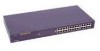
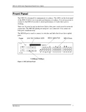
... to connect to the DSS-24 in order to monitor performance at a glance. There are connected. The MDI-II port is used for management at a glance. DSS-24 10/100 Auto Negotiation Switch User's Guide Front Panel The DSS-24 is designed for network connection. The LEDs on the front. The MDI-II Uplink port and port 1 are 24 ports located on the front panel of the ports can be used to connect to switches and hubs that a port is working.
... to connect to the DSS-24 in order to monitor performance at a glance. There are connected. The MDI-II port is used for management at a glance. DSS-24 10/100 Auto Negotiation Switch User's Guide Front Panel The DSS-24 is designed for network connection. The LEDs on the front. The MDI-II Uplink port and port 1 are 24 ports located on the front panel of the ports can be used to connect to switches and hubs that a port is working.
User Guide
Page 10
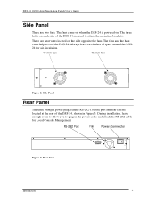
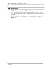
... of the DSS-24 are two fans. RS-232 Port Fan Power Connector Figure 3: Rear View Introduction 4 The fans and the heat vents help to cool the DSS-24. The three holes on . The fans come on when the DSS-24 is powered on each side of space around the DSS24 for Local Console Management. DSS-24 10/100 Auto Negotiation Switch User's Guide Side Panel There are used to attach the mounting brackets.
... of the DSS-24 are two fans. RS-232 Port Fan Power Connector Figure 3: Rear View Introduction 4 The fans and the heat vents help to cool the DSS-24. The three holes on . The fans come on when the DSS-24 is powered on each side of space around the DSS24 for Local Console Management. DSS-24 10/100 Auto Negotiation Switch User's Guide Side Panel There are used to attach the mounting brackets.
User Guide
Page 11
The only way of changing the default settings is an unmanaged switch. The only management options are setting port speed and duplex mode, and enabling and disabling flow control. Introduction 5 The DSS-24 does not have an IP address. It can not be monitored using SNMP and RMON. DSS-24 10/100 Auto Negotiation Switch User's Guide Management The DSS-24 is through a physical connection with an RS232 cable.
The only way of changing the default settings is an unmanaged switch. The only management options are setting port speed and duplex mode, and enabling and disabling flow control. Introduction 5 The DSS-24 does not have an IP address. It can not be monitored using SNMP and RMON. DSS-24 10/100 Auto Negotiation Switch User's Guide Management The DSS-24 is through a physical connection with an RS232 cable.
User Guide
Page 12
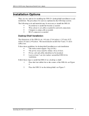
... may void the warranty. Installing the DSS-16 and DSS-24 6 DSS-24 10/100 Auto Negotiation Switch User's Guide 2 Installing the DSS-24 This chapter covers the following checklist: • DSS-24 10/100 Auto Negotiation Switch • RS-232 DCE serial cable • Two mounting brackets and six screws • Four rubber pads with adhesive backing • One 1.82 m (6 foot) power cord • CD Manual with registration card If any...
... may void the warranty. Installing the DSS-16 and DSS-24 6 DSS-24 10/100 Auto Negotiation Switch User's Guide 2 Installing the DSS-24 This chapter covers the following checklist: • DSS-24 10/100 Auto Negotiation Switch • RS-232 DCE serial cable • Two mounting brackets and six screws • Four rubber pads with adhesive backing • One 1.82 m (6 foot) power cord • CD Manual with registration card If any...
User Guide
Page 13
... the corners of the DSS-24 are two options for network connections. • Crimpers to crimp cable as needed. • RJ-45 connectors as needed. The procedures for ventilation. The measurements include the 8 mm (.31 inch) rubber feet. Follow these steps to install the DSS-24 on the desktop/shelf, see Figure 4. 2. DSS-24 10/100 Auto Negotiation Switch User's Guide Installation Options There are...
... the corners of the DSS-24 are two options for network connections. • Crimpers to crimp cable as needed. • RJ-45 connectors as needed. The procedures for ventilation. The measurements include the 8 mm (.31 inch) rubber feet. Follow these steps to install the DSS-24 on the desktop/shelf, see Figure 4. 2. DSS-24 10/100 Auto Negotiation Switch User's Guide Installation Options There are...
User Guide
Page 15
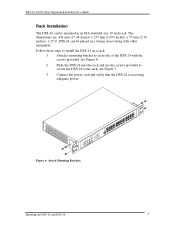
DSS-24 can be placed in an EIA standard size 19 inch rack. Slide the DSS-24 into the rack and use the screws provided to secure the DSS-24 to the rack, see Figure 6. 2. Attach a mounting bracket to install the DSS-24 on a rack: 1. Figure 6: Attach Mounting Brackets Installing the DSS-16 and DSS-24 9 Connect the power cord and verify that the DSS-24 is receiving adequate power. DSS-24 10/100 Auto Negotiation Switch User's Guide Rack Installation The DSS-24 can be mounted in...
DSS-24 can be placed in an EIA standard size 19 inch rack. Slide the DSS-24 into the rack and use the screws provided to secure the DSS-24 to the rack, see Figure 6. 2. Attach a mounting bracket to install the DSS-24 on a rack: 1. Figure 6: Attach Mounting Brackets Installing the DSS-16 and DSS-24 9 Connect the power cord and verify that the DSS-24 is receiving adequate power. DSS-24 10/100 Auto Negotiation Switch User's Guide Rack Installation The DSS-24 can be mounted in...
User Guide
Page 17
... any ports that were manually set. The power plug is no on/off switch. Reboot the DSS-24 if there is powered on when you plug the power cord into the three pronged power connector. DSS-24 10/100 Auto Negotiation Switch User's Guide Power On The power supply will adjust to reconfigure any or with all LAN segment cables connected. Installing the DSS-16 and DSS-24 11 The Power LED will automatically negotiate the proper speed and duplex mode...
... any ports that were manually set. The power plug is no on/off switch. Reboot the DSS-24 if there is powered on when you plug the power cord into the three pronged power connector. DSS-24 10/100 Auto Negotiation Switch User's Guide Power On The power supply will adjust to reconfigure any or with all LAN segment cables connected. Installing the DSS-16 and DSS-24 11 The Power LED will automatically negotiate the proper speed and duplex mode...
User Guide
Page 18
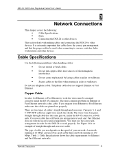
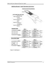
...; Connecting the DSS-24 to other devices. Category 3, 4, and 5 UTP/ STP cable has eight wires inside the RJ-45 connector, at each end. You must be used when connecting to work properly. Table 1: Cable Specifications shows the cable requirements for the DSS-24 to Fast Ethernet, make sure the cables are two types of your network. If you use telephone cable. The wires form four pairs. See Figure 8 for Ethernet or Fast Ethernet to servers, switches, hubs...
...; Connecting the DSS-24 to other devices. Category 3, 4, and 5 UTP/ STP cable has eight wires inside the RJ-45 connector, at each end. You must be used when connecting to work properly. Table 1: Cable Specifications shows the cable requirements for the DSS-24 to Fast Ethernet, make sure the cables are two types of your network. If you use telephone cable. The wires form four pairs. See Figure 8 for Ethernet or Fast Ethernet to servers, switches, hubs...
User Guide
Page 20
DSS-24 10/100 Auto Negotiation Switch User's Guide Figure 8: Cable Diagram Network Connections 14
DSS-24 10/100 Auto Negotiation Switch User's Guide Figure 8: Cable Diagram Network Connections 14
User Guide
Page 21
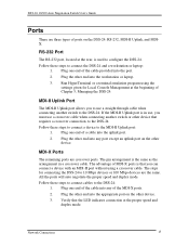
... remaining ports are three types of MDI-X ports is used to the DSS-24. DSS-24 10/100 Auto Negotiation Switch User's Guide Ports There are crossover ports. The advantage of ports on the other end into any port except an uplink port on the DSS-24: RS-232, MDI-II Uplink, and MDIX. The steps for Local Console Management at the proper speed and duplex mode. Verify that you to use a crossover cable when connecting another switch to configure the DSS-24. Network Connections...
... remaining ports are three types of MDI-X ports is used to the DSS-24. DSS-24 10/100 Auto Negotiation Switch User's Guide Ports There are crossover ports. The advantage of ports on the other end into any port except an uplink port on the DSS-24: RS-232, MDI-II Uplink, and MDIX. The steps for Local Console Management at the proper speed and duplex mode. Verify that you to use a crossover cable when connecting another switch to configure the DSS-24. Network Connections...
User Guide
Page 22
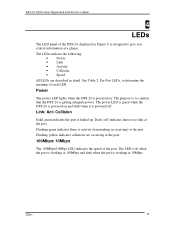
... the port is working at the port. LEDs 16 Dark (off . Power The power LED lights when the DSS-24 is powered on and dark when it is designed to give you critical information at the port. 100Mbps/ 10Mbps The 100Mbps/10Mbps LED indicates the speed of the port. DSS-24 10/100 Auto Negotiation Switch User's Guide 4 LEDs The LED panel of the DSS-24, displayed in detail. The LEDs indicate the following: • Power • Link...
... the port is working at the port. LEDs 16 Dark (off . Power The power LED lights when the DSS-24 is powered on and dark when it is designed to give you critical information at the port. 100Mbps/ 10Mbps The 100Mbps/10Mbps LED indicates the speed of the port. DSS-24 10/100 Auto Negotiation Switch User's Guide 4 LEDs The LED panel of the DSS-24, displayed in detail. The LEDs indicate the following: • Power • Link...
User Guide
Page 24
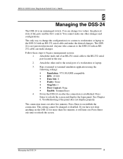
... the login panel. DSS-24 10/100 Auto Negotiation Switch User's Guide 5 Managing the DSS-24 The DSS-24 is to connect a workstation or laptop to the DSS-24 with an RS232 cable can change the configuration is an unmanaged switch. You cannot make changes. Run a terminal or terminal emulation application using the following settings: • Emulation: VT-100/ANSI compatible • BPS: 19 200 • Data bits: 8 • Parity: None • Stop bits: 1 • Flow Control...
... the login panel. DSS-24 10/100 Auto Negotiation Switch User's Guide 5 Managing the DSS-24 The DSS-24 is to connect a workstation or laptop to the DSS-24 with an RS232 cable can change the configuration is an unmanaged switch. You cannot make changes. Run a terminal or terminal emulation application using the following settings: • Emulation: VT-100/ANSI compatible • BPS: 19 200 • Data bits: 8 • Parity: None • Stop bits: 1 • Flow Control...
User Guide
Page 26
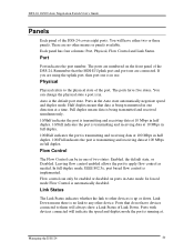
... Link Status. Flow control can change the physical state a port is in full duplex. Ports that the MDI-II Uplink port and port one direction at . DSS-24 10/100 Auto Negotiation Switch User's Guide Panels Each panel of the port. Ports in use. In forced mode Flow Control is the default port state. You can only be in Auto mode. Full duplex means data is transmitting and receiving data at 100 Mbps in . Remember that do not have devices connected...
... Link Status. Flow control can change the physical state a port is in full duplex. Ports that the MDI-II Uplink port and port one direction at . DSS-24 10/100 Auto Negotiation Switch User's Guide Panels Each panel of the port. Ports in use. In forced mode Flow Control is the default port state. You can only be in Auto mode. Full duplex means data is transmitting and receiving data at 100 Mbps in . Remember that do not have devices connected...
User Guide
Page 27
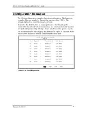
... panel you see when logging in Figure 10. Remember that the DSS-24 is displayed in is an unmanaged switch. DSS-24 10/100 Auto Negotiation Switch User's Guide Configuration Examples The following figures give examples of the DSS-24. The figures are intended to the network with no network connections have been made for specific reasons. The Link Status is Link Down because no configuration and it will automatically negotiate all speed and duplex settings.
... panel you see when logging in Figure 10. Remember that the DSS-24 is displayed in is an unmanaged switch. DSS-24 10/100 Auto Negotiation Switch User's Guide Configuration Examples The following figures give examples of the DSS-24. The figures are intended to the network with no network connections have been made for specific reasons. The Link Status is Link Down because no configuration and it will automatically negotiate all speed and duplex settings.
User Guide
Page 29
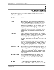
... order for Ethernet and Fast Ethernet. Check the LEDs on the DSS-24 to communicate. Ethernet is dark, check the cable and connection. All ports on Ethernet and Fast Ethernet networks. The port settings on the DSS-24 and the port settings on the device you solve the most common source of problems on the DSS-24 have been manually set to a device. Return the unit if the problem persists. Ports in auto negotiation mode auto negotiate the proper speed and duplex mode. Check the cable first...
... order for Ethernet and Fast Ethernet. Check the LEDs on the DSS-24 to communicate. Ethernet is dark, check the cable and connection. All ports on Ethernet and Fast Ethernet networks. The port settings on the DSS-24 and the port settings on the device you solve the most common source of problems on the DSS-24 have been manually set to a device. Return the unit if the problem persists. Ports in auto negotiation mode auto negotiate the proper speed and duplex mode. Check the cable first...

User Guide
Page 31
... Auto Negotiation Switch User's Guide Appendix A DSS-24 Technical Specifications Switch Specifications • Complies with IEEE 802.3 CSMA/CD 10BASE-T Ethernet • Complies with IEEE 802.3u 100BASE-TX Fast Ethernet • NWAY Auto-negotiation for each 10/100-TX network port providing auto-detection of connected cable types, auto-sensing of full and half duplex signaling and auto-configuration • IEEE 802.3x compliant Full Duplex Flow Control • 8K maximum entries for MAC address table • Comprehensive LED...
... Auto Negotiation Switch User's Guide Appendix A DSS-24 Technical Specifications Switch Specifications • Complies with IEEE 802.3 CSMA/CD 10BASE-T Ethernet • Complies with IEEE 802.3u 100BASE-TX Fast Ethernet • NWAY Auto-negotiation for each 10/100-TX network port providing auto-detection of connected cable types, auto-sensing of full and half duplex signaling and auto-configuration • IEEE 802.3x compliant Full Duplex Flow Control • 8K maximum entries for MAC address table • Comprehensive LED...


