Product Manual
Page 9
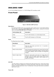
D-Link DSS-200G MP/MPP series Switch User Manual DSS-200G-10MP 8 x 10/100/1000 Mbps PoE ports + 2 x 100/1000 Mbps SFP surveillance switch Front Panel Figure 2-1 DSS-200G-10MP Front Panel Mode Button: By pressing the Mode button over 2 seconds, the Port LED (ports 1~8) will erase all flash orange) to ...Alert LED: The Alert indicator is blinking red to indicate PoE malfunctioning events: PoE function startup failure, PoE function disabled due to the below Link/Act/Speed LED) and PoE mode to indicate the PoE ports (refer to thermal abnormality, PoE power denial, PoE power overload, and PoE...
D-Link DSS-200G MP/MPP series Switch User Manual DSS-200G-10MP 8 x 10/100/1000 Mbps PoE ports + 2 x 100/1000 Mbps SFP surveillance switch Front Panel Figure 2-1 DSS-200G-10MP Front Panel Mode Button: By pressing the Mode button over 2 seconds, the Port LED (ports 1~8) will erase all flash orange) to ...Alert LED: The Alert indicator is blinking red to indicate PoE malfunctioning events: PoE function startup failure, PoE function disabled due to the below Link/Act/Speed LED) and PoE mode to indicate the PoE ports (refer to thermal abnormality, PoE power denial, PoE power overload, and PoE...
Product Manual
Page 12
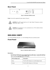
Rear Panel D-Link DSS-200G MP/MPP series Switch User Manual Figure 2-2 DSS-200G-10MP Rear Panel Power: Connect the supplied AC power cable to the below Link/Act/Speed LED) and PoE mode to indicate the PoE ports (refer to this port. DSS-200G-10MPP 8 x 10/100/1000 Mbps PoE ports + 2 x 100/1000 Mbps SFP ports surveillance switch Front...
Rear Panel D-Link DSS-200G MP/MPP series Switch User Manual Figure 2-2 DSS-200G-10MP Rear Panel Power: Connect the supplied AC power cable to the below Link/Act/Speed LED) and PoE mode to indicate the PoE ports (refer to this port. DSS-200G-10MPP 8 x 10/100/1000 Mbps PoE ports + 2 x 100/1000 Mbps SFP ports surveillance switch Front...
Product Manual
Page 27
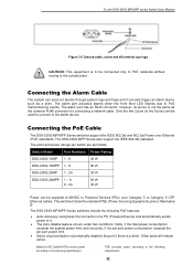
...Link DSS-200G MP/MPP series Switch User Manual Figure 3-5 Ground cable, screw and #8 terminal lug rings CAUTION: This equipment is to be used to connect to the alarm device. and secondly, if the per port power consumption exceeds the per switch are as follows: Switch Model Port Numbers Power Rating DSS-200G-10MP 1 - 8 30 W DSS-200G...-10MPP 1 - 8 90 W DSS-200G-28MP 1 - 24 30 W DSS-200G-28MPP 1 - 8 9 - 24 90 W 30 W Power can send out alarms ...
...Link DSS-200G MP/MPP series Switch User Manual Figure 3-5 Ground cable, screw and #8 terminal lug rings CAUTION: This equipment is to be used to connect to the alarm device. and secondly, if the per port power consumption exceeds the per switch are as follows: Switch Model Port Numbers Power Rating DSS-200G-10MP 1 - 8 30 W DSS-200G...-10MPP 1 - 8 90 W DSS-200G-28MP 1 - 24 30 W DSS-200G-28MPP 1 - 8 9 - 24 90 W 30 W Power can send out alarms ...

Product Manual
Page 28
... 1/2&7/8 are negative (V-); DSS-200G-10MP / DSS-200G-28MP DSS-200G-10MP (ports 1-8) / DSS-200G-28MP (ports 1-24): These ports support 802.3af/at the speed of 10 Mbps. For the last 16 ports (ports 9-24), Pin 4/5 is positive (V+) and Pin 7/8 is negative (compliant with 802.3at). DSS-200G-10MPP / DSS-200G-28MPP DSS-200G-10MPP (ports 1-8) / DSS-200G-28MPP (ports 1-24): Ports 1-8 of DSS-200G-10MPP and DSS-200G-28MPP support 802...
... 1/2&7/8 are negative (V-); DSS-200G-10MP / DSS-200G-28MP DSS-200G-10MP (ports 1-8) / DSS-200G-28MP (ports 1-24): These ports support 802.3af/at the speed of 10 Mbps. For the last 16 ports (ports 9-24), Pin 4/5 is positive (V+) and Pin 7/8 is negative (compliant with 802.3at). DSS-200G-10MPP / DSS-200G-28MPP DSS-200G-10MPP (ports 1-8) / DSS-200G-28MPP (ports 1-24): Ports 1-8 of DSS-200G-10MPP and DSS-200G-28MPP support 802...

Product Manual
Page 94
... this function is enabled, the Poe PD-alive function of the device. When a PD is disconnected, the PoE will be configured are ports 1-4 of DSS-200G-10MP/10MPP and ports 1-8 of the controlled port is enabled or disabled on the front of the controlled port is enabled (go to supply power through... of the DIP switch located on the switch. Check the Isolation function is enabled. After STP is enabled, the STP function on the switch. D-Link DSS-200G MP/MPP series Switch User Manual Dip Switch Dip Status Extend (250M@10Mbps) Dip Status This window is to the PD. If the restart fails...
... this function is enabled, the Poe PD-alive function of the device. When a PD is disconnected, the PoE will be configured are ports 1-4 of DSS-200G-10MP/10MPP and ports 1-8 of the controlled port is enabled or disabled on the front of the controlled port is enabled (go to supply power through... of the DIP switch located on the switch. Check the Isolation function is enabled. After STP is enabled, the STP function on the switch. D-Link DSS-200G MP/MPP series Switch User Manual Dip Switch Dip Status Extend (250M@10Mbps) Dip Status This window is to the PD. If the restart fails...
Product Manual
Page 95
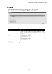
Ports that can be configured are described below: Parameter Description Port Enable the DIP switch of the port Extend State for the PoE function. D-Link DSS-200G MP/MPP series Switch User Manual Extend This window is to save the configuration. 90 To view the following window, click Dip Switch > Extend, as ...shown below: Figure 4-66 Port Extend Status window The fields that can be configured with the PoE Extend functions: DSS-200G-10MP: 1-4 port. Click Apply to view the status of the port Extend function on the switch...
Ports that can be configured are described below: Parameter Description Port Enable the DIP switch of the port Extend State for the PoE function. D-Link DSS-200G MP/MPP series Switch User Manual Extend This window is to save the configuration. 90 To view the following window, click Dip Switch > Extend, as ...shown below: Figure 4-66 Port Extend Status window The fields that can be configured with the PoE Extend functions: DSS-200G-10MP: 1-4 port. Click Apply to view the status of the port Extend function on the switch...

Product Manual
Page 109
... and system information. On the left the total bandwidth shows the total inbound traffic on the right, showing the inbound traffic for each individual port. D-Link DSS-200G MP/MPP series Switch User Manual Device Information This is the second tab on the model number of the switch at the top of the... is divided into 3 sections; To view the following window, click on the Surveillance Overview page and is CPU usage percentage recorded every 10 seconds. Note: DSS-200G-10MP does not have fans, the Rotating speed are not shown. 104
... and system information. On the left the total bandwidth shows the total inbound traffic on the right, showing the inbound traffic for each individual port. D-Link DSS-200G MP/MPP series Switch User Manual Device Information This is the second tab on the model number of the switch at the top of the... is divided into 3 sections; To view the following window, click on the Surveillance Overview page and is CPU usage percentage recorded every 10 seconds. Note: DSS-200G-10MP does not have fans, the Rotating speed are not shown. 104
Product Manual
Page 123
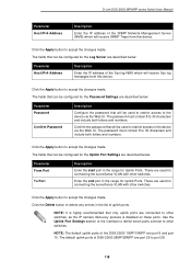
... Port Settings section of the interface to define which ports connect to accept the changes made . NOTE: The default uplink ports of the DSS-200G-10MP/10MPP are described below : Parameter From Port To Port Description Enter the start port in the range for Uplink Ports. Click the Apply...Enter the end port in the range for Uplink Ports. Click the Apply button to 30 characters and include both letters and numbers. D-Link DSS-200G MP/MPP series Switch User Manual Parameter Host IPv4 Address Description Enter the IP address of the SNMP Network Management Server (NMS) which will...
... Port Settings section of the interface to define which ports connect to accept the changes made . NOTE: The default uplink ports of the DSS-200G-10MP/10MPP are described below : Parameter From Port To Port Description Enter the start port in the range for Uplink Ports. Click the Apply...Enter the end port in the range for Uplink Ports. Click the Apply button to 30 characters and include both letters and numbers. D-Link DSS-200G MP/MPP series Switch User Manual Parameter Host IPv4 Address Description Enter the IP address of the SNMP Network Management Server (NMS) which will...

Product Manual
Page 133
....2dB PoE input 0-77W, 1936PM: 26.1dB 128 Supports IEEE 802.3x Flow Control - DSS-200G-10MP: 9.53 W - IEEE 802.3ab - DSS-200G-10MP: 9.63 W (POE OFF) 160.2 W (POE ON) - DSS-200G-28MPP: 23.52 W (POE OFF) 579.3 W (POE ON) Standby Power Consumption - IEEE 802.3u compliance - D-Link DSS-200G MP/MPP Series Switch User Manual 7. Forwarding Rate: -DSS-200G-10MP: 14.88Mpps - DSS-200G-10MP: 4.1Mbits -
....2dB PoE input 0-77W, 1936PM: 26.1dB 128 Supports IEEE 802.3x Flow Control - DSS-200G-10MP: 9.53 W - IEEE 802.3ab - DSS-200G-10MP: 9.63 W (POE OFF) 160.2 W (POE ON) - DSS-200G-28MPP: 23.52 W (POE OFF) 579.3 W (POE ON) Standby Power Consumption - IEEE 802.3u compliance - D-Link DSS-200G MP/MPP Series Switch User Manual 7. Forwarding Rate: -DSS-200G-10MP: 14.88Mpps - DSS-200G-10MP: 4.1Mbits -


