Product Manual
Page 4
TABLE OF CONTENTS About This Guide 6 Purpose 6 Terms/Usage 6 Introduction 7 Fast Ethernet Technology 7 Switching Technology 7 VLAN (Virtual Local Area Network 8 Power over Ethernet (PoE 9 Features 9 Unpacking and Installation 11 Unpacking 11 Installation 11 Rack Mounting 12 Connecting Network Cable 13 AC Power 13 Identifying External Components 14 Front Panel 14 Rear Panel 15 Understanding LED Indicators 16 Power and CPU LEDs 16 Ports 1~8 PoE port status LEDs 16 Ports 9~16 Ethernet port status LEDs 17 4
TABLE OF CONTENTS About This Guide 6 Purpose 6 Terms/Usage 6 Introduction 7 Fast Ethernet Technology 7 Switching Technology 7 VLAN (Virtual Local Area Network 8 Power over Ethernet (PoE 9 Features 9 Unpacking and Installation 11 Unpacking 11 Installation 11 Rack Mounting 12 Connecting Network Cable 13 AC Power 13 Identifying External Components 14 Front Panel 14 Rear Panel 15 Understanding LED Indicators 16 Power and CPU LEDs 16 Ports 1~8 PoE port status LEDs 16 Ports 9~16 Ethernet port status LEDs 17 4

Product Manual
Page 5
Configuration 18 Installing the Web Management Utility 18 Discovery List 20 Monitor List 21 Device Setting 23 Toolbar 25 Configuring the Switch 26 Login 27 Setup Menu 30 Configuring Setup Setting 31 Port Settings 31 VLAN Settings (Virtual Local Area Network 33 Trunk Setting 35 Mirror Setting 36 PoE Setting 37 Device Status 39 Statistic 40 System Setting 42 Trap Setting 43 Set Password 44 Backup Setting 45 Reset Setting 46 Logout 46 Technical Specifications 48 5
Configuration 18 Installing the Web Management Utility 18 Discovery List 20 Monitor List 21 Device Setting 23 Toolbar 25 Configuring the Switch 26 Login 27 Setup Menu 30 Configuring Setup Setting 31 Port Settings 31 VLAN Settings (Virtual Local Area Network 33 Trunk Setting 35 Mirror Setting 36 PoE Setting 37 Device Status 39 Statistic 40 System Setting 42 Trap Setting 43 Set Password 44 Backup Setting 45 Reset Setting 46 Logout 46 Technical Specifications 48 5

Product Manual
Page 6
... this Switch's Port-1 to Port-8 are Power over Ethernet (PoE) ports, it will automatically detect the presence of the 8-Port 10/100Mbps Ethernet Web Smart Switch with 8 10/100Mbps PoE ports and "switch" (first letter lower case) refers to WLAN access point, IP phone, video camera, and other Ethernet switches. 6 This Switch integrates 100Mbps Fast Ethernet and 10Mbps Ethernet network capabilities in a highly flexible package. The Switch provides 15.4Watts per port and can be connected to...
... this Switch's Port-1 to Port-8 are Power over Ethernet (PoE) ports, it will automatically detect the presence of the 8-Port 10/100Mbps Ethernet Web Smart Switch with 8 10/100Mbps PoE ports and "switch" (first letter lower case) refers to WLAN access point, IP phone, video camera, and other Ethernet switches. 6 This Switch integrates 100Mbps Fast Ethernet and 10Mbps Ethernet network capabilities in a highly flexible package. The Switch provides 15.4Watts per port and can be connected to...

Product Manual
Page 7
... complexity of the Web Smart Switch and some background information about Ethernet/Fast Ethernet switching technology. Switching Technology Another approach to provide greater bandwidth and improve client/server response times. It is the development of the existing investment in hardware, software, and personnel training. Among them, 100BASE-T (Fast Ethernet) provides a non-disruptive, smooth evolution from the current 10BASE-T technology. A number of high-speed LAN technologies have...
... complexity of the Web Smart Switch and some background information about Ethernet/Fast Ethernet switching technology. Switching Technology Another approach to provide greater bandwidth and improve client/server response times. It is the development of the existing investment in hardware, software, and personnel training. Among them, 100BASE-T (Fast Ethernet) provides a non-disruptive, smooth evolution from the current 10BASE-T technology. A number of high-speed LAN technologies have...
Product Manual
Page 8
... and decreases network loading by dividing a local area network into different segments, which were characterized by their physical location and can communicate as a high-speed selective bridge between the individual segments. The switch acts as if a common broadcast domain, a LAN. Routers have also been used to only those confidential users within the VLAN. 8 transmitting among connected Ethernet or Fast Ethernet LAN segments...
... and decreases network loading by dividing a local area network into different segments, which were characterized by their physical location and can communicate as a high-speed selective bridge between the individual segments. The switch acts as if a common broadcast domain, a LAN. Routers have also been used to only those confidential users within the VLAN. 8 transmitting among connected Ethernet or Fast Ethernet LAN segments...

Product Manual
Page 9
...% of VLANs across multiple switches. (Reference: IEEE Std 802.1Q-1998 Virtual Bridged Local Area Networks.) Power over Ethernet (PoE) Power over cables or an up to 100 Meters, PoE will provide power to PoE compatible device, such as IP telephones, wireless LAN access points, and IP security cameras. Features 16×10/100Mbps Auto-negotiation Fast Ethernet RJ45 ports with 8-port PoE function (port-1 ~ port-8) Compliant with 802.3af specification Supports PoE power maximum 15...
...% of VLANs across multiple switches. (Reference: IEEE Std 802.1Q-1998 Virtual Bridged Local Area Networks.) Power over Ethernet (PoE) Power over cables or an up to 100 Meters, PoE will provide power to PoE compatible device, such as IP telephones, wireless LAN access points, and IP security cameras. Features 16×10/100Mbps Auto-negotiation Fast Ethernet RJ45 ports with 8-port PoE function (port-1 ~ port-8) Compliant with 802.3af specification Supports PoE power maximum 15...

Product Manual
Page 10
...Store-and-Forward switching scheme capability to support rate adaptation and ensure data integrity Up to 4K unicast addresses entities per device, self-learning, and table aging 512KBytes packet buffer Supports IEEE 802.3x flow control for full-duplex mode ports Supports Back-pressure flow control for half-duplex mode ports Supports 802.1Q VLAN Supports Port based Trunking Supports Port-mirroring Supports Port-setting for Speed/Disable, Flow control and Port based QoS (Quality of Service) Easy configuration via Web Browser Easy setting via Web Management Utility Standard 19" Rack-mount size 10
...Store-and-Forward switching scheme capability to support rate adaptation and ensure data integrity Up to 4K unicast addresses entities per device, self-learning, and table aging 512KBytes packet buffer Supports IEEE 802.3x flow control for full-duplex mode ports Supports Back-pressure flow control for half-duplex mode ports Supports 802.1Q VLAN Supports Port based Trunking Supports Port-mirroring Supports Port-setting for Speed/Disable, Flow control and Port based QoS (Quality of Service) Easy configuration via Web Browser Easy setting via Web Management Utility Standard 19" Rack-mount size 10
Product Manual
Page 13
.... Connecting Network Cable The Switch supports 16 10/100M Ethernet ports and Port 1 ~ 8 are not yet compatible, the PoE port will not offer the power to these devices. For Legacy devices that without having any or all LAN segment cables connected. 13 The power switch is identified. This feature allows users to the AC power connector and the system fan. These PoE ports will supply power through the Ethernet port to the connected PoE device. duplex mode using a standard...
.... Connecting Network Cable The Switch supports 16 10/100M Ethernet ports and Port 1 ~ 8 are not yet compatible, the PoE port will not offer the power to these devices. For Legacy devices that without having any or all LAN segment cables connected. 13 The power switch is identified. This feature allows users to the AC power connector and the system fan. These PoE ports will supply power through the Ethernet port to the connected PoE device. duplex mode using a standard...

Product Manual
Page 14
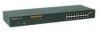
... panels of the Switch. duplex transfer modes. LED Indicator: Comprehensive LED indicators display the status of 16-port 10/100 Ethernet Switch with 8-port PoE. These ports also support the automatic MDI/MDIX crossover detection function, providing true "plug and play" capability. These ports support network speeds of either 10Mbps or 100Mbps, and can operate in the network cable to these devices. The PoE port will supply power through the Ethernet port to freely and...
... panels of the Switch. duplex transfer modes. LED Indicator: Comprehensive LED indicators display the status of 16-port 10/100 Ethernet Switch with 8-port PoE. These ports also support the automatic MDI/MDIX crossover detection function, providing true "plug and play" capability. These ports support network speeds of either 10Mbps or 100Mbps, and can operate in the network cable to these devices. The PoE port will supply power through the Ethernet port to freely and...

Product Manual
Page 15
... the factory defaults. Rear panel of the Switch AC Power Connector: This is to reset all settings will be erased when pressing the "Reset" button. 15 duplex transfer modes. Rear Panel Reset Button AC Power Connector Figure 4. Reset: The Reset button is a three-pronged connector that you recorded the settings of your device, else all settings back to "Forced Mode", Auto MDI/MDIX will be disabled. Plug in half- Ethernet Ports (Port 9~16): These ports support network speeds...
... the factory defaults. Rear panel of the Switch AC Power Connector: This is to reset all settings will be erased when pressing the "Reset" button. 15 duplex transfer modes. Rear Panel Reset Button AC Power Connector Figure 4. Reset: The Reset button is a three-pronged connector that you recorded the settings of your device, else all settings back to "Forced Mode", Auto MDI/MDIX will be disabled. Plug in half- Ethernet Ports (Port 9~16): These ports support network speeds...

Product Manual
Page 16
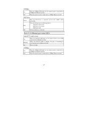
... On : When the Power LED lights on, the Switch is transmitting or receiving data on , the respective port is blinking. Off : When the Power turns off or the power cord has improper connection. Figure 5. UNDERSTANDING LED INDICATORS The front panel LEDs provide instant status feedback, and helps monitor and troubleshoot when needed. CPU: Management Indicator Blinking : When the CPU is working . Ports 1~8 PoE port status LEDs Link/ACT: Link/Activity On : When the Link/ACT LED lights on the Ethernet network.
... On : When the Power LED lights on, the Switch is transmitting or receiving data on , the respective port is blinking. Off : When the Power turns off or the power cord has improper connection. Figure 5. UNDERSTANDING LED INDICATORS The front panel LEDs provide instant status feedback, and helps monitor and troubleshoot when needed. CPU: Management Indicator Blinking : When the CPU is working . Ports 1~8 PoE port status LEDs Link/ACT: Link/Activity On : When the Link/ACT LED lights on the Ethernet network.
Product Manual
Page 17
... respective port is connected to a 100Mbps Fast Ethernet network. Ports 9~16 Ethernet port status LEDs Link/ACT: Link/Activity On Blinking : When the Link/ACT LED lights on, the respective port is successfully connected to an Ethernet network. : When the Link/ACT LED is blinking, the port is connected to a 10Mbps Ethernet network. 17 device is connected and the port supplies power When the PoE port has the following failures: Red : PoE power short circuit PoE Power over current PoE Power fault Off : No Powered Device is connected to a 10Mbps Ethernet network. Off...
... respective port is connected to a 100Mbps Fast Ethernet network. Ports 9~16 Ethernet port status LEDs Link/ACT: Link/Activity On Blinking : When the Link/ACT LED lights on, the respective port is successfully connected to an Ethernet network. : When the Link/ACT LED is blinking, the port is connected to a 10Mbps Ethernet network. 17 device is connected and the port supplies power When the PoE port has the following failures: Red : PoE power short circuit PoE Power over current PoE Power fault Off : No Powered Device is connected to a 10Mbps Ethernet network. Off...

Product Manual
Page 18
... to install the utility. 5. Installing the Web Management Utility The following instructions guide you can easily discover all the Web Management Switches, assign the IP Address, changing the password, and upgrade new firmware. Insert the Utility CD in the CD-ROM Drive. 2. etc. From the Start menu on -screen instructions to Program Files -> web_management_utility and execute the Web Management utility. (Figure 6.) 18 In the Run dialog box, type D:\Web Management Utility\setup...
... to install the utility. 5. Installing the Web Management Utility The following instructions guide you can easily discover all the Web Management Switches, assign the IP Address, changing the password, and upgrade new firmware. Insert the Utility CD in the CD-ROM Drive. 2. etc. From the Start menu on -screen instructions to Program Files -> web_management_utility and execute the Web Management utility. (Figure 6.) 18 In the Run dialog box, type D:\Web Management Utility\setup...

Product Manual
Page 21
.... Subnet Mask: Shows the Subnet Mask set of the device. View Trap: The Trap function can also receive the trap and show the status of the Web-Smart device, represents a device system that happen on the Web Management Switch in the Monitor List. 21 MAC Address: Shows the device MAC Address. IP Address: Shows the current IP address of the device. Gateway: Shows the Gateway set of the device.
.... Subnet Mask: Shows the Subnet Mask set of the device. View Trap: The Trap function can also receive the trap and show the status of the Web-Smart device, represents a device system that happen on the Web Management Switch in the Monitor List. 21 MAC Address: Shows the device MAC Address. IP Address: Shows the current IP address of the device. Gateway: Shows the Gateway set of the device.

Product Manual
Page 23
... using the function key in the password and press the "Set" button to process the data change , you want to change immediately. 23 Select the device in the Monitor List. After filling in the data that you must fill in the Device Setting Dialog box. Add Item: To add a device to the Monitor List manually, enter the IP Address of the device that you want to monitor. Delete Item: To delete...
... using the function key in the password and press the "Set" button to process the data change , you want to change immediately. 23 Select the device in the Monitor List. After filling in the data that you must fill in the Device Setting Dialog box. Add Item: To add a device to the Monitor List manually, enter the IP Address of the device that you want to monitor. Delete Item: To delete...
Product Manual
Page 26
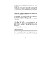
... view log and clear log functions, the view log function will help you to select the time for smart switch configuration. In the "Option TAB", there is About function, it will show out the version of the Monitor List to an appointed filename and file path. Configuring the Switch The 16-Port 10/100Mbps Ethernet Web Smart Switch with 8-Port PoE has a Web GUI interface for monitoring. Exit: To exit the Web Management Utility. Monitor Load: To manually load the setting file...
... view log and clear log functions, the view log function will help you to select the time for smart switch configuration. In the "Option TAB", there is About function, it will show out the version of the Monitor List to an appointed filename and file path. Configuring the Switch The 16-Port 10/100Mbps Ethernet Web Smart Switch with 8-Port PoE has a Web GUI interface for monitoring. Exit: To exit the Web Management Utility. Monitor Load: To manually load the setting file...

Product Manual
Page 27
... enable its smart functions including: Port Setting (Speed/Disable, and Flow Control) VLAN Setting (802.1Q VLAN) Trunking Port Mirroring PoE Setting System Setting Device status and Statistic Login Before you configure this device, note that when the Web Smart Switch is configured through an Ethernet connection, make sure the manager PC is set at 192.168.0.x (where x is a number between 2 and 254), and the default subnet mask is 192.168.0.1, then the manager PC should be set on same the IP network...
... enable its smart functions including: Port Setting (Speed/Disable, and Flow Control) VLAN Setting (802.1Q VLAN) Trunking Port Mirroring PoE Setting System Setting Device status and Statistic Login Before you configure this device, note that when the Web Smart Switch is configured through an Ethernet connection, make sure the manager PC is set at 192.168.0.x (where x is a number between 2 and 254), and the default subnet mask is 192.168.0.1, then the manager PC should be set on same the IP network...
Product Manual
Page 33
... settings, VID Table Setting and Port VLAN Setting. You can control traffic flow and ease the administration of switch ports that need to change physical cabling. When you create a VLAN, you set. To remove the selected VID group, select the VID group and press "Remove the VID" button. VLAN Settings (Virtual Local Area Network) A VLAN is a collection of moves, adds, and changes on the network, by eliminating the need to have a high priority to manage the data transfer, QoS...
... settings, VID Table Setting and Port VLAN Setting. You can control traffic flow and ease the administration of switch ports that need to change physical cabling. When you create a VLAN, you set. To remove the selected VID group, select the VID group and press "Remove the VID" button. VLAN Settings (Virtual Local Area Network) A VLAN is a collection of moves, adds, and changes on the network, by eliminating the need to have a high priority to manage the data transfer, QoS...

Product Manual
Page 36
... sniffer mode is connected to keep close track of each incoming and/or outgoing packet from which to another port where the packet can be sent. It enables the manager to the device with a same VLAN group. Figure 20. Trunk Settings Be sure that forwards a copy of switch performance and alter it if necessary. Configuring the port mirroring by assigning a source port from one port of monitoring network traffic that...
... sniffer mode is connected to keep close track of each incoming and/or outgoing packet from which to another port where the packet can be sent. It enables the manager to the device with a same VLAN group. Figure 20. Trunk Settings Be sure that forwards a copy of switch performance and alter it if necessary. Configuring the port mirroring by assigning a source port from one port of monitoring network traffic that...

Product Manual
Page 46
the IP address of 192.168.0.1. Backup Setting Note: When restoring a recorded file, the current password will be reset; Be aware that the entire configuration will log out and return to the default setting from the factory. Figure 31. Reset Setting The Factory Reset button helps you select this function, the Web configuration will be set to the default setting of the device will not be erased. Reset Setting Logout When you to reset the device back to first Login page. 46 Figure 30.
the IP address of 192.168.0.1. Backup Setting Note: When restoring a recorded file, the current password will be reset; Be aware that the entire configuration will log out and return to the default setting from the factory. Figure 31. Reset Setting The Factory Reset button helps you select this function, the Web configuration will be set to the default setting of the device will not be erased. Reset Setting Logout When you to reset the device back to first Login page. 46 Figure 30.


