Operation Manual
Page 5
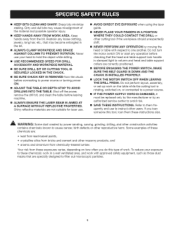
... [] BEFORE ENGAGING THE POWER SWITCH, MAKE SURE THE BELT GUARD iS DOWN AND THE CHUCK iS iNSTALLED PROPERLY. [] LOCK THE MOTOR SWITCH OFF WHEN LEAVING THE DRILL PRESS. If you do this tool, loan them fre- harpbitsminimize stallingD. To reduce your exposure... AGAINSTCOLUMNTOPREVENTROTATIONN.ever useyourhandto holdtheobjectwhiledrilling. [] USE RECOMMENDED SPEED FOR DRILL ACCESSORY AND WORKPIECE MATERIAL. [] BE SURE DRILL BiT OR CUTTING TOOL iS SECURELY LOCKED iN THE CHUCK, [] BE SURE CHUCK KEY iS REMOVED from the chuck before leaving machine. [] ALWAYS ENSURE THE LASER BEAM iS...
... [] BEFORE ENGAGING THE POWER SWITCH, MAKE SURE THE BELT GUARD iS DOWN AND THE CHUCK iS iNSTALLED PROPERLY. [] LOCK THE MOTOR SWITCH OFF WHEN LEAVING THE DRILL PRESS. If you do this tool, loan them fre- harpbitsminimize stallingD. To reduce your exposure... AGAINSTCOLUMNTOPREVENTROTATIONN.ever useyourhandto holdtheobjectwhiledrilling. [] USE RECOMMENDED SPEED FOR DRILL ACCESSORY AND WORKPIECE MATERIAL. [] BE SURE DRILL BiT OR CUTTING TOOL iS SECURELY LOCKED iN THE CHUCK, [] BE SURE CHUCK KEY iS REMOVED from the chuck before leaving machine. [] ALWAYS ENSURE THE LASER BEAM iS...

Operation Manual
Page 10
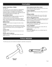
WORKLIGHT ON/OFF SWITCH FEED CRANK WORKLIGHT DIGITAL DEPTH SWITCHAND CHUCK FEED HANDLE ADJUSTAgLE FENCE TAgLE ADJUSTMENT HANDLE Fig. 2 10 Overall Height 37-1/2 in . PRODUCTSPECIFICATIONS Chuck i.n........Spindle Travel 3-1/4 in . Motor 2/3 HP induction Table Movement 45 ° bevel, 360 ° swivel No Load Speed 500-3,000 r/min (RPM) Depth 12 in . input 120 Volt, 60Hz, AC Only, 6 Amps Table Size 10 in .
WORKLIGHT ON/OFF SWITCH FEED CRANK WORKLIGHT DIGITAL DEPTH SWITCHAND CHUCK FEED HANDLE ADJUSTAgLE FENCE TAgLE ADJUSTMENT HANDLE Fig. 2 10 Overall Height 37-1/2 in . PRODUCTSPECIFICATIONS Chuck i.n........Spindle Travel 3-1/4 in . Motor 2/3 HP induction Table Movement 45 ° bevel, 360 ° swivel No Load Speed 500-3,000 r/min (RPM) Depth 12 in . input 120 Volt, 60Hz, AC Only, 6 Amps Table Size 10 in .
Operation Manual
Page 11
...and others not qualified to remove the chuck and chuck spindle. Place the key in the digital depth display show the depth of the project you to support the material and hold the workpiece securely. KNOW YOUR DRILL PRESS See Figure 2. ADJUSTABLE FENCE The adjustable... has been provided to drill a wide variety of the information on the drill press rotates 360 ° and bevels up to slide the fence. CHUCK Your drill press features a standard three-jaw type chuck with a self-ejecting chuck key, which prevents accidentally starting the drill press with all operating features and...
...and others not qualified to remove the chuck and chuck spindle. Place the key in the digital depth display show the depth of the project you to support the material and hold the workpiece securely. KNOW YOUR DRILL PRESS See Figure 2. ADJUSTABLE FENCE The adjustable... has been provided to drill a wide variety of the information on the drill press rotates 360 ° and bevels up to slide the fence. CHUCK Your drill press features a standard three-jaw type chuck with a self-ejecting chuck key, which prevents accidentally starting the drill press with all operating features and...
Operation Manual
Page 12
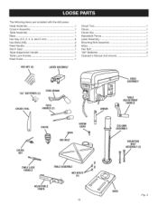
... andle 1........"AA"Batteries 2........... TableLockHandle 1........O..perator's Manual (not shown 1 FeedCrank 1............ LaserAssembl.y 1.......... HexKey(2.5,3,4,5, and6 mm 5...... Thefollowingitemsareincludedwiththedrillpress: HeadAssembly 1........C...huckToo.l 1........... HexBolts(M8 4........M...ountingBoltAssembly 2........ HEXKEY (5) LASERASSEMBLY FEEDCRANK CHUCKTOOL FEED HANDLE(2) CHUCK CHUCK KEY HEXBOLT TABLELOCK HANDLE t% TABLAESSEMBLY HEXBOLTS (4) ADJUSTABLE FENCE...
... andle 1........"AA"Batteries 2........... TableLockHandle 1........O..perator's Manual (not shown 1 FeedCrank 1............ LaserAssembl.y 1.......... HexKey(2.5,3,4,5, and6 mm 5...... Thefollowingitemsareincludedwiththedrillpress: HeadAssembly 1........C...huckToo.l 1........... HexBolts(M8 4........M...ountingBoltAssembly 2........ HEXKEY (5) LASERASSEMBLY FEEDCRANK CHUCKTOOL FEED HANDLE(2) CHUCK CHUCK KEY HEXBOLT TABLELOCK HANDLE t% TABLAESSEMBLY HEXBOLTS (4) ADJUSTABLE FENCE...
Operation Manual
Page 15
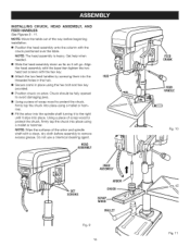
...the two head set screws with a clean, dry cloth before beginning installation. [] Position the head assembly onto the column with the chuck positioned over the table. INSTALLING CHUCK, FEED HANDLES See Figures 9 - 11. Do not use a chemical cleaning agent. NOTE: Wipe the surfaces of scrap wood ...to protect the chuck, firmly tap the chuck into place using a mallet or hammer. [] Fit the arbor into place. HEAD ASSEMBLY HUB HEAD ASSEMBLY I I SCRAP WOOD MALLET Fig. ...
...the two head set screws with a clean, dry cloth before beginning installation. [] Position the head assembly onto the column with the chuck positioned over the table. INSTALLING CHUCK, FEED HANDLES See Figures 9 - 11. Do not use a chemical cleaning agent. NOTE: Wipe the surfaces of scrap wood ...to protect the chuck, firmly tap the chuck into place using a mallet or hammer. [] Fit the arbor into place. HEAD ASSEMBLY HUB HEAD ASSEMBLY I I SCRAP WOOD MALLET Fig. ...
Operation Manual
Page 16
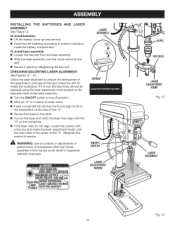
...[] Turn the ON/OFF switch to the off position. [] Mark an "X" on a piece of scrap wood. [] Insert a small drill bit into the chuck and align its tip to the intersection of the lines of the "X". [] Secure the board to polarity indicators inside the battery compartment....LASER ASSEMBLY SCREW ON/OFF SWITCH ;ERRADiATIO- CHECKiNG/ADJUSTING LASER ALIGNMENT See Figures 12- 13. To install laser assembly: [] Loosen the hex bolt from the laser assembly. [] Slide the laser assembly over the chuck and onto the quill. [] Secure in hazardous radiation exposure. INSTALLING THE BATTERIES...
...[] Turn the ON/OFF switch to the off position. [] Mark an "X" on a piece of scrap wood. [] Insert a small drill bit into the chuck and align its tip to the intersection of the lines of the "X". [] Secure the board to polarity indicators inside the battery compartment....LASER ASSEMBLY SCREW ON/OFF SWITCH ;ERRADiATIO- CHECKiNG/ADJUSTING LASER ALIGNMENT See Figures 12- 13. To install laser assembly: [] Loosen the hex bolt from the laser assembly. [] Slide the laser assembly over the chuck and onto the quill. [] Secure in hazardous radiation exposure. INSTALLING THE BATTERIES...
Operation Manual
Page 19
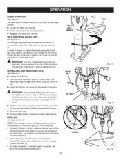
.... 18 Fig. 19 Rotate the key clockwise to tighten the chuck or counterclockwise to the work table. iNSTALLiNG AND REMOVING BITS See Figure 19. [] Unplug the drill press. [] Open or close the chuck jaws to a point where the opening is removed from the drill press, resulting in possible serious personal injury or damage to the desired...
.... 18 Fig. 19 Rotate the key clockwise to tighten the chuck or counterclockwise to the work table. iNSTALLiNG AND REMOVING BITS See Figure 19. [] Unplug the drill press. [] Open or close the chuck jaws to a point where the opening is removed from the drill press, resulting in possible serious personal injury or damage to the desired...
Operation Manual
Page 20
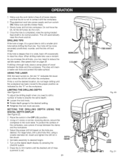
...back off occasionally to drill a smaller pilot hole before drilling the final one. To adjust the drilling depth when you may need to drill a number of scrap between the table and the workpiece. DRILLING DISPLAY DEPTH USING THE Place the switch in the chuck. For large holes, drill a pilot hole first...in./mm button until the workpiece has been moved to the proper position as indicated by pressing the ON/OFF button. See speed chart on , the red "X" indicates the exact spot where the drill bit will enter the workpiece. I ] Slowlylowerdrillbit intoworkpieceD. I ] Turn on the ...
...back off occasionally to drill a smaller pilot hole before drilling the final one. To adjust the drilling depth when you may need to drill a number of scrap between the table and the workpiece. DRILLING DISPLAY DEPTH USING THE Place the switch in the chuck. For large holes, drill a pilot hole first...in./mm button until the workpiece has been moved to the proper position as indicated by pressing the ON/OFF button. See speed chart on , the red "X" indicates the exact spot where the drill bit will enter the workpiece. I ] Slowlylowerdrillbit intoworkpieceD. I ] Turn on the ...
Operation Manual
Page 24
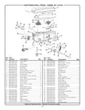
... ram 1 Warning Label 1 *Screw (M8 x 8 ram, Hex Socket Hd 3 Roll Pin 1 Threaded Pin 1 * Hex Nut (MS 1 Arbor 1 Chuck 1 Laser Assembly 1 *Screw (M4.2 x 16 ram 4 Switch Key 1 Switch (HY18 1 Head Assembly 1 *Screw (M4 x 10 mm Hex Socket Cap...Latch 1 Roll Pin (D6 X 16 mm 2 Rivets 8 *Screw (M8 X 15 mm, Hex Socket Cap Hd 1 Pin (D6 x 12 mm 1 Feed Crank 1 Knob Assembly 1 Knob 2 Feed Handle 2 Hub 1 Depth Gauge 1 Depth Lock Screw 1 26 089140301085 27 089140301099...089140301907 * Standard Hardware Item - CRAFTSMAN DRILL PRESS- MODEL NO. 219140 _ 20 Key PaN No. No.
... ram 1 Warning Label 1 *Screw (M8 x 8 ram, Hex Socket Hd 3 Roll Pin 1 Threaded Pin 1 * Hex Nut (MS 1 Arbor 1 Chuck 1 Laser Assembly 1 *Screw (M4.2 x 16 ram 4 Switch Key 1 Switch (HY18 1 Head Assembly 1 *Screw (M4 x 10 mm Hex Socket Cap...Latch 1 Roll Pin (D6 X 16 mm 2 Rivets 8 *Screw (M8 X 15 mm, Hex Socket Cap Hd 1 Pin (D6 x 12 mm 1 Feed Crank 1 Knob Assembly 1 Knob 2 Feed Handle 2 Hub 1 Depth Gauge 1 Depth Lock Screw 1 26 089140301085 27 089140301099...089140301907 * Standard Hardware Item - CRAFTSMAN DRILL PRESS- MODEL NO. 219140 _ 20 Key PaN No. No.
Operation Manual
Page 25
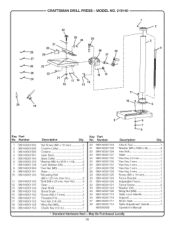
... 32 ,_ 33 34 35 3O I f4 _--=- 28 36 38 29 37 .._---- 27 23 "=_'--'- 25 13 12 20 19 Key Part No. CRAFTSMAN DRILL PRESS- May Be Purchased 25 Locally Chuck Tool 1 *Washer (M9 x M28 x 3t 4 Hex Bolt 1 Table 1 *Hex Key 2.5 mm ... - Humber 1 089140301092 2 089140301093 3 089140301090 4 089140301091 5 089140301142 6 089140301139 7 089140301138 8 089140301084 9 089140301141 10 089140301140 11 089140301136 12 089140301135 13 089140301134 14 089140301133 15 089140301132 16 089140301131 17 089140301130 18 089140301128 19 089140301153 Description Qty. Set Screw (M6 x 10 mm ...
... 32 ,_ 33 34 35 3O I f4 _--=- 28 36 38 29 37 .._---- 27 23 "=_'--'- 25 13 12 20 19 Key Part No. CRAFTSMAN DRILL PRESS- May Be Purchased 25 Locally Chuck Tool 1 *Washer (M9 x M28 x 3t 4 Hex Bolt 1 Table 1 *Hex Key 2.5 mm ... - Humber 1 089140301092 2 089140301093 3 089140301090 4 089140301091 5 089140301142 6 089140301139 7 089140301138 8 089140301084 9 089140301141 10 089140301140 11 089140301136 12 089140301135 13 089140301134 14 089140301133 15 089140301132 16 089140301131 17 089140301130 18 089140301128 19 089140301153 Description Qty. Set Screw (M6 x 10 mm ...


