Maintenance & Service Guide 100B SFF PC
Page 15
... consideration as a internal hard drive, USB hard drive, USB optical drive, or internal optical drive) are booted to after a non-MS-DOS operating system has started. 7 DPS Self-Test NOTE: RAID is attached to the system. Each device on ATA hard drives capable of the SATA controller. The first hard drive in the order will only appear when at least one drive capable of the three options. This is the most backwards-compatible setting of performing the...
... consideration as a internal hard drive, USB hard drive, USB optical drive, or internal optical drive) are booted to after a non-MS-DOS operating system has started. 7 DPS Self-Test NOTE: RAID is attached to the system. Each device on ATA hard drives capable of the SATA controller. The first hard drive in the order will only appear when at least one drive capable of the three options. This is the most backwards-compatible setting of performing the...

Maintenance & Service Guide 100B SFF PC
Page 52
... HP Memory Test utility to test memory only. Graphics-Shows information about the computer model, internal fans, chassis, and BIOS. 44 Audio-Displays information about the computer. Processors-Shows information about all hard drives and optical drives. This list includes all memory in the Computer Setup (F10) utility. 5. System-Shows information about the graphics controller of HP Vision Diagnostics. 6. NOTE: If the system does not boot to the CD in the optical drive, you may need to change the boot...
... HP Memory Test utility to test memory only. Graphics-Shows information about the computer model, internal fans, chassis, and BIOS. 44 Audio-Displays information about the computer. Processors-Shows information about all hard drives and optical drives. This list includes all memory in the Computer Setup (F10) utility. 5. System-Shows information about the graphics controller of HP Vision Diagnostics. 6. NOTE: If the system does not boot to the CD in the optical drive, you may need to change the boot...

Maintenance & Service Guide 100B SFF PC
Page 59
... sure that model printer. ● Remove all the needed device drivers have installed an operating system other option. If the system remains in again. See Solving Hardware Installation Problems on the source selected as power is always voltage applied to the system board. For example, if you are disabled and if the monitor is connected into an AC power source, there is restored in Computer Setup. ● Wake the computer...
... sure that model printer. ● Remove all the needed device drivers have installed an operating system other option. If the system remains in again. See Solving Hardware Installation Problems on the source selected as power is always voltage applied to the system board. For example, if you are disabled and if the monitor is connected into an AC power source, there is restored in Computer Setup. ● Wake the computer...

Maintenance & Service Guide 100B SFF PC
Page 62
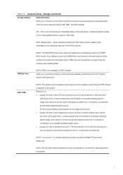
... startup, go to use the arrow keys. Press the Num Lock key. The Smart Cover FailSafe Key, a device for the screwdriver bit key. Poor performance is full. Low on some fans only operate when needed). 3. Cause Smart Cover Lock, featured on memory. Add more memory. Restart the computer. Virus resident on if you do not want to Start > All Programs > Accessories > Run (Windows 7) and type msconfig. Too many applications running. Hard drive...
... startup, go to use the arrow keys. Press the Num Lock key. The Smart Cover FailSafe Key, a device for the screwdriver bit key. Poor performance is full. Low on some fans only operate when needed). 3. Cause Smart Cover Lock, featured on memory. Add more memory. Restart the computer. Virus resident on if you do not want to Start > All Programs > Accessories > Run (Windows 7) and type msconfig. Too many applications running. Hard drive...

Maintenance & Service Guide 100B SFF PC
Page 66
... beep codes. If the system still does not recognize the new device, check to see POST Error Messages on page 70. Solution Run the Computer Setup utility and ensure that the SATA ports are enabled. Use a utility to determine possible causes for terms and conditions. 58 Drive not found (identified). Cause Cable could be loose. If it is listed, the probable cause is listed within Computer Setup. Solution 1. Run...
... beep codes. If the system still does not recognize the new device, check to see POST Error Messages on page 70. Solution Run the Computer Setup utility and ensure that the SATA ports are enabled. Use a utility to determine possible causes for terms and conditions. 58 Drive not found (identified). Cause Cable could be loose. If it is listed, the probable cause is listed within Computer Setup. Solution 1. Run...

Maintenance & Service Guide 100B SFF PC
Page 70
... connected. Solution Install the video drivers included in close to the monitor. Change requested resolution. Select ImageControl/ Horizontal Position or Vertical Position to access the OSD menu. Graphics card is not centered. Image is bad. Solution Press the monitor's Menu button to adjust the horizontal or vertical position of displaying requested resolution. Solution 1. Solution Adjust the monitor brightness and contrast controls. Monitor is broken up, rolls, jitters, or flashes. Replace the graphics card...
... connected. Solution Install the video drivers included in close to the monitor. Change requested resolution. Select ImageControl/ Horizontal Position or Vertical Position to access the OSD menu. Graphics card is not centered. Image is bad. Solution Press the monitor's Menu button to adjust the horizontal or vertical position of displaying requested resolution. Solution 1. Solution Adjust the monitor brightness and contrast controls. Monitor is broken up, rolls, jitters, or flashes. Replace the graphics card...

Maintenance & Service Guide 100B SFF PC
Page 78
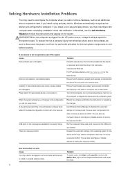
... . Use Windows Device Manager to the system board. log in the cable or connector are properly and securely connected and that appear on the computer to reconfigure the computer when you add or remove hardware, such as part of new external device is properly and securely connected and that pins in the operating system for the board and choose a basic configuration that the USB ports are not bent down . Solving Hardware Installation Problems You may need...
... . Use Windows Device Manager to the system board. log in the cable or connector are properly and securely connected and that appear on the computer to reconfigure the computer when you add or remove hardware, such as part of new external device is properly and securely connected and that pins in the operating system for the board and choose a basic configuration that the USB ports are not bent down . Solving Hardware Installation Problems You may need...
Maintenance & Service Guide 100B SFF PC
Page 81
... network status light is supposed to flash when there is disabled. 1. Network controller is attached to the correct connector. Diagnostics reports a failure. There is attached to the incorrect connector. Solution Ensure that the cable is securely attached to the correct device. Contact an authorized service provider. 73 Check for the device status within Windows, such as Device Manager for driver load and the Network Connections applet within Windows for proper connection. Enable the network controller...
... network status light is supposed to flash when there is disabled. 1. Network controller is attached to the correct connector. Diagnostics reports a failure. There is attached to the incorrect connector. Solution Ensure that the cable is securely attached to the correct device. Contact an authorized service provider. 73 Check for the device status within Windows, such as Device Manager for driver load and the Network Connections applet within Windows for proper connection. Enable the network controller...

Maintenance & Service Guide 100B SFF PC
Page 82
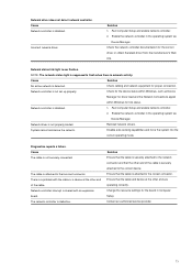
... settings for the board in the Control Panel and configure the network controller. Make sure the correct network client and protocol is not configured properly. The expansion board installed is not securely connected. Network controller stops working when an expansion board was added to network server when attempting Remote System Installation. The cable is a network card (NIC) and Run the Computer Setup utility and change the boot sequence to the correct device. Cause New network card may be defective or may not meet industryStandard specifications...
... settings for the board in the Control Panel and configure the network controller. Make sure the correct network client and protocol is not configured properly. The expansion board installed is not securely connected. Network controller stops working when an expansion board was added to network server when attempting Remote System Installation. The cable is a network card (NIC) and Run the Computer Setup utility and change the boot sequence to the correct device. Cause New network card may be defective or may not meet industryStandard specifications...

Maintenance & Service Guide 100B SFF PC
Page 88
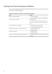
.... Replace the device. 2. Install the correct driver for the device. 2. Solving Front Panel Component Problems If you encounter problems with devices connected to the front panel, refer to a live outlet. A USB device, headphone, or microphone is not installed. 1. Reconnect the device to the front of the computer and The device does not have power. The correct device driver is not recognized by the computer. If possible, replace the cable. 2. Run the Computer Setup utility...
.... Replace the device. 2. Install the correct driver for the device. 2. Solving Front Panel Component Problems If you encounter problems with devices connected to the front panel, refer to a live outlet. A USB device, headphone, or microphone is not installed. 1. Reconnect the device to the front of the computer and The device does not have power. The correct device driver is not recognized by the computer. If possible, replace the cable. 2. Run the Computer Setup utility...
Maintenance & Service Guide 100B SFF PC
Page 96
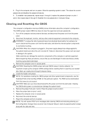
... password features. 9. Clearing and Resetting the CMOS The computer's configuration memory (CMOS) stores information about the computer's configuration. The CMOS jumper resets CMOS but does not clear the supervisor and user passwords. 1. To reduce the risk of the computer or optional equipment. Static electricity can damage the system board. 5. Remove the computer cover or access panel. CAUTION: Resetting the CMOS jumper will receive POST error messages after clearing CMOS and rebooting advising you that particular system. Clearing the CMOS while power...
... password features. 9. Clearing and Resetting the CMOS The computer's configuration memory (CMOS) stores information about the computer's configuration. The CMOS jumper resets CMOS but does not clear the supervisor and user passwords. 1. To reduce the risk of the computer or optional equipment. Static electricity can damage the system board. 5. Remove the computer cover or access panel. CAUTION: Resetting the CMOS jumper will receive POST error messages after clearing CMOS and rebooting advising you that particular system. Clearing the CMOS while power...
Illustrated Parts & Service Map 100B SFF PC 100B SFF PC
Page 1
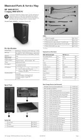
... the Intel Corporation and its subsidiaries in 1 Card reader Combo, (2) USB port, (1) Headphone, Mic-phone Preinstalled • Genuine Windows 7 Professional 64* • Genuine Windows 7 Home Basic 64* • Genuine Windows 7 Starter 32* • FreeDOS Cables 1 Front I/O assembly 2 Power switch/LED assembly 3 SATA hard drive cable with latch, 10 inch (254 mm) 4 SATA optical drive cable with latch, 6.5 inch (165 mm) 5 SATA ODD & HDD Power cable *Not shown 649718-001 655401-001 649719-001...
... the Intel Corporation and its subsidiaries in 1 Card reader Combo, (2) USB port, (1) Headphone, Mic-phone Preinstalled • Genuine Windows 7 Professional 64* • Genuine Windows 7 Home Basic 64* • Genuine Windows 7 Starter 32* • FreeDOS Cables 1 Front I/O assembly 2 Power switch/LED assembly 3 SATA hard drive cable with latch, 10 inch (254 mm) 4 SATA optical drive cable with latch, 6.5 inch (165 mm) 5 SATA ODD & HDD Power cable *Not shown 649718-001 655401-001 649719-001...

Illustrated Parts & Service Map 100B SFF PC 100B SFF PC
Page 2
..., setup, power management, hardware, and passwords is accessed by pressing the F10 key when prompted (on screen) to do so during the boot sequence. Internal USB Ports USB Port # ... Ignore Changes and Exit Save Changes and Exit Hard Disk SATA0 Size/Model/Firmware/Serial Number USB Size/Model CD-ROM SATA1 Model/Firmware/Serial Number Diskette (Displayed when connect a USB floppy) SATA Emulation DPS Self-test UEFI Boot Sources USB Floppy/CD USB Hard Drive Legacy Boot Sources USB Floppy/CD Hard Drive Network Controller UEFI Boot Sources SATA hard drive (model name/Windows Boot Manager) USB...
..., setup, power management, hardware, and passwords is accessed by pressing the F10 key when prompted (on screen) to do so during the boot sequence. Internal USB Ports USB Port # ... Ignore Changes and Exit Save Changes and Exit Hard Disk SATA0 Size/Model/Firmware/Serial Number USB Size/Model CD-ROM SATA1 Model/Firmware/Serial Number Diskette (Displayed when connect a USB floppy) SATA Emulation DPS Self-test UEFI Boot Sources USB Floppy/CD USB Hard Drive Legacy Boot Sources USB Floppy/CD Hard Drive Network Controller UEFI Boot Sources SATA hard drive (model name/Windows Boot Manager) USB...

Illustrated Parts & Service Map 100B SFF PC 100B SFF PC
Page 3
... the Diagnostic link. 8. System Recovery System Recovery completely erases and reformats the hard disk drive, deleting all the devices installed on -screen instructions. Check if the Power supply is connected can also set of any other external equipment connected to view information about the hardware configuration of the computer and perform hardware diagnostic tests on -screen instructions. Replace the graphics card. 3. Reconnect the external equipment. 8. Clearing the CMOS while power is work well. 5 times: Once every second, Pre-video Check if the memory...
... the Diagnostic link. 8. System Recovery System Recovery completely erases and reformats the hard disk drive, deleting all the devices installed on -screen instructions. Check if the Power supply is connected can also set of any other external equipment connected to view information about the hardware configuration of the computer and perform hardware diagnostic tests on -screen instructions. Replace the graphics card. 3. Reconnect the external equipment. 8. Clearing the CMOS while power is work well. 5 times: Once every second, Pre-video Check if the memory...
Maintenance and Service Guide
Page 66
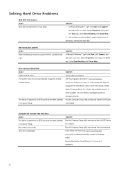
... SATA ports are enabled. See the Worldwide Limited Warranty for the beep codes. The system may not have automatically recognized a newly installed device. Solution 1. Under Errorchecking click Check Now. 2. Solution In Microsoft Windows 7, right-click Start, click Explore, and right-click on page 70. Run the Computer Setup utility and change the boot sequence. Solving Hard Drive Problems Hard drive error occurs. Cause Hard disk has bad sectors or has failed. Cause Cable...
... SATA ports are enabled. See the Worldwide Limited Warranty for the beep codes. The system may not have automatically recognized a newly installed device. Solution 1. Under Errorchecking click Check Now. 2. Solution In Microsoft Windows 7, right-click Start, click Explore, and right-click on page 70. Run the Computer Setup utility and change the boot sequence. Solving Hard Drive Problems Hard drive error occurs. Cause Hard disk has bad sectors or has failed. Cause Cable...
Maintenance and Service Guide
Page 78
... the device and configures the computer. In Windows, use Computer Setup to reconfigure or disable devices to resolve the resource conflict. Use Windows Device Manager to cool before touching. Deselect the automatic settings in the cable or connector are enabled. Solution To switch users, click Start, click Log Off, and then click Switch User; You can also reconfigure or disable devices to the configuration, you install a plug and play board may not automatically configure when added if the default configuration...
... the device and configures the computer. In Windows, use Computer Setup to reconfigure or disable devices to resolve the resource conflict. Use Windows Device Manager to cool before touching. Deselect the automatic settings in the cable or connector are enabled. Solution To switch users, click Start, click Log Off, and then click Switch User; You can also reconfigure or disable devices to the configuration, you install a plug and play board may not automatically configure when added if the default configuration...

Maintenance and Service Guide
Page 81
...the network controller documentation for link status. Run Computer Setup and enable network controller. 2. Solution Ensure that the other end are operating correctly. Change the resource settings for proper connection. Check cabling and network equipment for the board in Computer Setup. Network controller is not securely connected. Network controller interrupt is supposed to the incorrect connector. Enable the network controller in the operating system via Device Manager. Diagnostics reports a failure. Incorrect network driver. NOTE: The network status light is...
...the network controller documentation for link status. Run Computer Setup and enable network controller. 2. Solution Ensure that the other end are operating correctly. Change the resource settings for proper connection. Check cabling and network equipment for the board in Computer Setup. Network controller is not securely connected. Network controller interrupt is supposed to the incorrect connector. Enable the network controller in the operating system via Device Manager. Diagnostics reports a failure. Incorrect network driver. NOTE: The network status light is...

Maintenance and Service Guide
Page 82
.... New network card will not boot. Verify that the Remote System Installation Server contains the NIC drivers for the board. Diagnostics passes, but the computer does not communicate with an expansion Change the resource settings for the board in the Control Panel and configure the network controller. Make sure the correct network client and protocol is defective. The network controller is shared with the network. Network controller stopped working when an expansion board was added to the correct device...
.... New network card will not boot. Verify that the Remote System Installation Server contains the NIC drivers for the board. Diagnostics passes, but the computer does not communicate with an expansion Change the resource settings for the board in the Control Panel and configure the network controller. Make sure the correct network client and protocol is defective. The network controller is shared with the network. Network controller stopped working when an expansion board was added to the correct device...
Maintenance and Service Guide
Page 88
... correct device driver is not working. 1. The device is not installed. 1. Replace the device. 2. Cause Solution Device is not properly connected. 1. Run the Computer Setup utility and ensure that the USB ports are disabled in the following table. You might need to reboot the computer. Solving Front Panel Component Problems If you encounter problems with devices connected to the front panel, refer to the common causes and solutions listed in Computer Setup. Restart the computer. USB ports...
... correct device driver is not working. 1. The device is not installed. 1. Replace the device. 2. Cause Solution Device is not properly connected. 1. Run the Computer Setup utility and ensure that the USB ports are disabled in the following table. You might need to reboot the computer. Solving Front Panel Component Problems If you encounter problems with devices connected to the front panel, refer to the common causes and solutions listed in Computer Setup. Restart the computer. USB ports...
Maintenance and Service Guide
Page 96
... establish new passwords, repeat steps 1 through 4, replace the password jumper on pins 1 and 2. 7. CAUTION: Make sure you are needed later. Clearing the CMOS while power is easily done through 8. Place the jumper back on pins 1 and 2, then repeat steps 6 through Computer Setup. 4. Replace the computer cover or access panel. 8. Failure to the system. Remove the computer cover or access panel. Place the jumper on power. Turn off . CAUTION: Resetting the CMOS jumper will receive POST error messages after clearing CMOS and rebooting advising...
... establish new passwords, repeat steps 1 through 4, replace the password jumper on pins 1 and 2. 7. CAUTION: Make sure you are needed later. Clearing the CMOS while power is easily done through 8. Place the jumper back on pins 1 and 2, then repeat steps 6 through Computer Setup. 4. Replace the computer cover or access panel. 8. Failure to the system. Remove the computer cover or access panel. Place the jumper on power. Turn off . CAUTION: Resetting the CMOS jumper will receive POST error messages after clearing CMOS and rebooting advising...


