
Hardware Maintenance Manual
Page 3
... operate its Sales or Service Partner in creating the environment in any form to any installation, handling, maintenance, or operating instructions supplied by Cisco, (3) has been subjected to unusual physical or electrical stress, misuse, negligence, or accident, (4) is error free or that Customer will be, at DFARS §252.2277013. AND ITS SUPPLIERS FROM TIME TO TIME, YOU AGREE TO...
... operate its Sales or Service Partner in creating the environment in any form to any installation, handling, maintenance, or operating instructions supplied by Cisco, (3) has been subjected to unusual physical or electrical stress, misuse, negligence, or accident, (4) is error free or that Customer will be, at DFARS §252.2277013. AND ITS SUPPLIERS FROM TIME TO TIME, YOU AGREE TO...

Hardware Maintenance Manual
Page 9
... 2-32 Cisco 4000 Series Chassis-Front Panel 1-2 Cisco 4000 Series Memory Systems and Software Images 1-4 Installation Checklist 2-5 Router-Rear View Showing Slot Numbering and Interface Ports 2-7 Router-Rear View Showing Serial Port Unit Numbering 2-8 Slot Filler Panel 2-9 Ethernet Network Processor Module with AUI and 10BaseT Connectors 2-11 Single-Port Ethernet Network Processor Module 10BaseT Port Connection 2-11 Single-Port Ethernet Network Processor Module AUI Port Connection 2-12 Extending the Transition Cable from the Ethernet Port 2-12 Dual-Port Ethernet Network Processor Module with...
... 2-32 Cisco 4000 Series Chassis-Front Panel 1-2 Cisco 4000 Series Memory Systems and Software Images 1-4 Installation Checklist 2-5 Router-Rear View Showing Slot Numbering and Interface Ports 2-7 Router-Rear View Showing Serial Port Unit Numbering 2-8 Slot Filler Panel 2-9 Ethernet Network Processor Module with AUI and 10BaseT Connectors 2-11 Single-Port Ethernet Network Processor Module 10BaseT Port Connection 2-11 Single-Port Ethernet Network Processor Module AUI Port Connection 2-12 Extending the Transition Cable from the Ethernet Port 2-12 Dual-Port Ethernet Network Processor Module with...

Hardware Maintenance Manual
Page 10
... AC-Input Power Supply-Rear View 3-20 DC-Input Power Supply Connections 3-21 Cisco 4000 Series-Front Panel Indicators 4-3 Dual-Port Ethernet Network Processor Module LEDs 4-4 Single-Port Ethernet Network Processor Module LEDs 4-4 Token Ring Module Network Connector 4-5 Four-Port Serial Network Processor Module Ports 4-6 G.703/G.704 Serial Network Processor Module Ports (DB-15) 4-6 Serial Port Labeled V2 4-7 Dual Serial Network Processor Module-Top View 4-8 Dual Serial Port LED Card-Side View 4-8 Dual-Attachment Single-Mode FDDI Module-End View 4-9 x Cisco 4000 Series Hardware Installation and...
... AC-Input Power Supply-Rear View 3-20 DC-Input Power Supply Connections 3-21 Cisco 4000 Series-Front Panel Indicators 4-3 Dual-Port Ethernet Network Processor Module LEDs 4-4 Single-Port Ethernet Network Processor Module LEDs 4-4 Token Ring Module Network Connector 4-5 Four-Port Serial Network Processor Module Ports 4-6 G.703/G.704 Serial Network Processor Module Ports (DB-15) 4-6 Serial Port Labeled V2 4-7 Dual Serial Network Processor Module-Top View 4-8 Dual Serial Port LED Card-Side View 4-8 Dual-Attachment Single-Mode FDDI Module-End View 4-9 x Cisco 4000 Series Hardware Installation and...

Hardware Maintenance Manual
Page 15
... Series Hardware Installation and Maintenance publication. Audience This publication is included in your local sales representative or call Customer Service. About This Manual xv Note To order UniverCD, Cisco's online library of the Cisco 4000 series features and physical specifications. • Chapter 2, "Preparing for Installation," includes safety recommendations, tools and equipment, site requirements, an installation checklist, console and auxiliary port cable connection considerations, network connection considerations, and instructions...
... Series Hardware Installation and Maintenance publication. Audience This publication is included in your local sales representative or call Customer Service. About This Manual xv Note To order UniverCD, Cisco's online library of the Cisco 4000 series features and physical specifications. • Chapter 2, "Preparing for Installation," includes safety recommendations, tools and equipment, site requirements, an installation checklist, console and auxiliary port cable connection considerations, network connection considerations, and instructions...

Hardware Maintenance Manual
Page 16
... or adding network processor modules, and replacing single in-line memory modules (SIMMs). • Appendix A, "Cabling Specifications," provides cable illustrations, cable pinouts, and signal descriptions for the console and auxiliary ports, synchronous serial cables, and Ethernet (AUI) cables. • Appendix B, "Cisco 4000 Series Virtual Configuration Register," describes the Cisco 4000-M virtual configuration register and procedures for changing the factory-default settings. • Appendix C, "Cisco 4000-M ROM Monitor," describes the Cisco 4000-M ROM monitor and how it can save time...
... or adding network processor modules, and replacing single in-line memory modules (SIMMs). • Appendix A, "Cabling Specifications," provides cable illustrations, cable pinouts, and signal descriptions for the console and auxiliary ports, synchronous serial cables, and Ethernet (AUI) cables. • Appendix B, "Cisco 4000 Series Virtual Configuration Register," describes the Cisco 4000-M virtual configuration register and procedures for changing the factory-default settings. • Appendix C, "Cisco 4000-M ROM Monitor," describes the Cisco 4000-M ROM monitor and how it can save time...

Hardware Maintenance Manual
Page 28
... modules - Intermittent problems - Use the Installation Checklist to reflect the following tools and equipment for the installation of the router: • ESD cord and wrist strap • Screwdrivers, Number 1 and Number 2 Phillips • One serial port adapter cable for multimode Fiber Distributed Data Interface (FDDI) connections. 2-6 Cisco 4000 Series Hardware Installation and Maintenance Site Log entries might need the following : - Removal or replacement of network processor modules - Maintenance procedures performed - Configuration changes - Site Log Site Log...
... modules - Intermittent problems - Use the Installation Checklist to reflect the following tools and equipment for the installation of the router: • ESD cord and wrist strap • Screwdrivers, Number 1 and Number 2 Phillips • One serial port adapter cable for multimode Fiber Distributed Data Interface (FDDI) connections. 2-6 Cisco 4000 Series Hardware Installation and Maintenance Site Log entries might need the following : - Removal or replacement of network processor modules - Maintenance procedures performed - Configuration changes - Site Log Site Log...

Hardware Maintenance Manual
Page 32
... CTRL/Z interface ethernet 0 media-type aui ^z router# write memory Refer to the router software publications for a Cisco 4000 series router. The syntax of the media command follows: media-type aui media-type aui 10baset The following sections describe the two types of AUI or 10BaseT on the module can be used at a time.) Use either an IEEE 802.3 AUI or a 10BaseT cable to configure your selection of Ethernet network processor modules: single-port and dual-port modules. Enter...
... CTRL/Z interface ethernet 0 media-type aui ^z router# write memory Refer to the router software publications for a Cisco 4000 series router. The syntax of the media command follows: media-type aui media-type aui 10baset The following sections describe the two types of AUI or 10BaseT on the module can be used at a time.) Use either an IEEE 802.3 AUI or a 10BaseT cable to configure your selection of Ethernet network processor modules: single-port and dual-port modules. Enter...

Hardware Maintenance Manual
Page 37
..., the most common interface standard in the United States, supports unbalanced circuits at signal speeds up your router, consider distance limitations and potential electromagnetic interference (EMI) as defined in Table 2-4 are subject to travel a limited distance at your own risk. however, the serial module ports support synchronous connections, and the console and auxiliary ports support asynchronous connections. Serial Line Distance Limitations Serial signals can compensate for each serial interface type; Table 2-4 EIA/TIA-232...
..., the most common interface standard in the United States, supports unbalanced circuits at signal speeds up your router, consider distance limitations and potential electromagnetic interference (EMI) as defined in Table 2-4 are subject to travel a limited distance at your own risk. however, the serial module ports support synchronous connections, and the console and auxiliary ports support asynchronous connections. Serial Line Distance Limitations Serial signals can compensate for each serial interface type; Table 2-4 EIA/TIA-232...

Hardware Maintenance Manual
Page 43
... on software commands, refer to the position shown in Figure 2-22 using the orientation shown in NRZI mode. Figure 2-22 Dual Serial Network Processor Module Jumpers, J4 and J5-NRZI Setting J5 J4 Pin 1 H1125a Port 1 Port 0 You must use a special serial cable to connect the router to a modem, CSU/DSU, or other device as DTE in Figure 2-21. An error message will be configured for Installation 2-21 Preparing for the module to...
... on software commands, refer to the position shown in Figure 2-22 using the orientation shown in NRZI mode. Figure 2-22 Dual Serial Network Processor Module Jumpers, J4 and J5-NRZI Setting J5 J4 Pin 1 H1125a Port 1 Port 0 You must use a special serial cable to connect the router to a modem, CSU/DSU, or other device as DTE in Figure 2-21. An error message will be configured for Installation 2-21 Preparing for the module to...
Hardware Maintenance Manual
Page 44
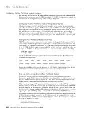
...: interface serial 1 clockrate 72000 Use the no clockrate command to accept the internal clock signal: interface serial 0 dce-terminal-timing-enable 2-22 Cisco 4000 Series Hardware Installation and Maintenance When a port is configured to remove the clock rate for NRZI encoding or 32-bit CRC. Slight variances in place of phase. In the example that follows, the serial 0 port is operating in DCE mode, you must connect a DCE interface cable and set...
...: interface serial 1 clockrate 72000 Use the no clockrate command to accept the internal clock signal: interface serial 0 dce-terminal-timing-enable 2-22 Cisco 4000 Series Hardware Installation and Maintenance When a port is configured to remove the clock rate for NRZI encoding or 32-bit CRC. Slight variances in place of phase. In the example that follows, the serial 0 port is operating in DCE mode, you must connect a DCE interface cable and set...

Hardware Maintenance Manual
Page 45
... complete command descriptions and instructions, refer to decode signals, rather than determining absolute values. Both formats use the show interface serial 0: Preparing for example, serial), and unit, the unit number of interface (for Installation 2-23 Network Connection Considerations To turn off this command inverts the clock signal to the remote DTE port. When the serial port is an error-checking technique that are used for NRZI encoding: router# configure terminal interface serial 0 nrzi-encoding ^Z To disable...
... complete command descriptions and instructions, refer to decode signals, rather than determining absolute values. Both formats use the show interface serial 0: Preparing for example, serial), and unit, the unit number of interface (for Installation 2-23 Network Connection Considerations To turn off this command inverts the clock signal to the remote DTE port. When the serial port is an error-checking technique that are used for NRZI encoding: router# configure terminal interface serial 0 nrzi-encoding ^Z To disable...
Hardware Maintenance Manual
Page 47
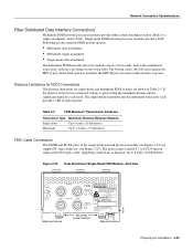
... 1 LASER PRODUCT LASERKLASSE 1 CISCO SYSTEMS, INC. 170 WEST TASMAN DRIVE SAN JOSE, CA 95134-1706 DATE: "Complies with one card fitting on the module's top card. Single-mode FDDI network processor modules provide a DAS. If the DAS option is included, the PHY-B port is located on top of optical power. Network Connection Considerations Fiber Distributed Data Interface Connections Multimode FDDI network processor modules provide either a dual-attachment station (DAS) or...
... 1 LASER PRODUCT LASERKLASSE 1 CISCO SYSTEMS, INC. 170 WEST TASMAN DRIVE SAN JOSE, CA 95134-1706 DATE: "Complies with one card fitting on the module's top card. Single-mode FDDI network processor modules provide a DAS. If the DAS option is included, the PHY-B port is located on top of optical power. Network Connection Considerations Fiber Distributed Data Interface Connections Multimode FDDI network processor modules provide either a dual-attachment station (DAS) or...

Hardware Maintenance Manual
Page 54
.... 2-32 Cisco 4000 Series Hardware Installation and Maintenance This interface is set with one E1 interface.The CE1 provides one channelized E1 connection via a serial cable to the system as a serial interface that supports ISDN PRI. Figure 2-34 Channelized E1 Network Interface Processor cE1 / PRI DB-15 female Following are the E1 specifications: • Transmission bit rate: 2.048 Mbps ± 50 ppm • Output port specifications: see...
.... 2-32 Cisco 4000 Series Hardware Installation and Maintenance This interface is set with one E1 interface.The CE1 provides one channelized E1 connection via a serial cable to the system as a serial interface that supports ISDN PRI. Figure 2-34 Channelized E1 Network Interface Processor cE1 / PRI DB-15 female Following are the E1 specifications: • Transmission bit rate: 2.048 Mbps ± 50 ppm • Output port specifications: see...
Hardware Maintenance Manual
Page 61
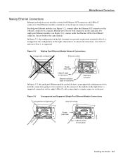
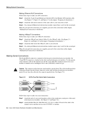
... connectors on the port. the configuration on the same module. Dual Ethernet modules contain two of each type of two network connections going to transceiver Installing the Router 3-3 Making Network Connections Making Ethernet Connections Ethernet network processor modules contain both on the right, which shows two network connections, one to Port 0 and one to Port 1, is unsupported; For dual-port Ethernet modules (see Figure 3-3), connect either the Ethernet AUI connector or the 10BaseT connector on a specific Ethernet port, but not both...
... connectors on the port. the configuration on the same module. Dual Ethernet modules contain two of each type of two network connections going to transceiver Installing the Router 3-3 Making Network Connections Making Ethernet Connections Ethernet network processor modules contain both on the right, which shows two network connections, one to Port 0 and one to Port 1, is unsupported; For dual-port Ethernet modules (see Figure 3-3), connect either the Ethernet AUI connector or the 10BaseT connector on a specific Ethernet port, but not both...
Hardware Maintenance Manual
Page 62
... network processor modules match. Ensure that orientation. Step 1 Attach the 15-pin D-type Ethernet port labeled AUI to the Ethernet AUI transition cable. (See Figure 2-7, Figure 2-8, and Figure 2-9 in the chapter "Preparing for Installation.") Step 2 Attach the other end of the cable to the channel service unit/data service unit (CSU/DSU) or modem. 3-4 Cisco 4000 Series Hardware Installation and Maintenance Making 10BaseT Connections Follow these steps to make your serial connections...
... network processor modules match. Ensure that orientation. Step 1 Attach the 15-pin D-type Ethernet port labeled AUI to the Ethernet AUI transition cable. (See Figure 2-7, Figure 2-8, and Figure 2-9 in the chapter "Preparing for Installation.") Step 2 Attach the other end of the cable to the channel service unit/data service unit (CSU/DSU) or modem. 3-4 Cisco 4000 Series Hardware Installation and Maintenance Making 10BaseT Connections Follow these steps to make your serial connections...

Hardware Maintenance Manual
Page 67
... made by users to timing slips. The BRI network processor module consists of the following sections before connecting the BRI port of a connect one -time-only plug) must be made to user contact. Installation Requirements (Special Considerations) Read the following subassemblies: • BRI network processor module mother card (part number 73-1219) • 1 or 2 BRI adapter interface cards (part number 73-1220) • BRI-ISDN (point-to-point use of your Cisco Systems...
... made by users to timing slips. The BRI network processor module consists of the following sections before connecting the BRI port of a connect one -time-only plug) must be made to user contact. Installation Requirements (Special Considerations) Read the following subassemblies: • BRI network processor module mother card (part number 73-1219) • 1 or 2 BRI adapter interface cards (part number 73-1220) • BRI-ISDN (point-to-point use of your Cisco Systems...
Hardware Maintenance Manual
Page 71
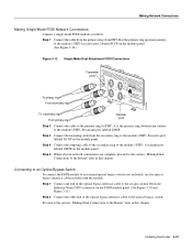
... ring Receiver ports Step 2 Connect the cable to the primary ring (to an external optical bypass switch (not included), use the optical bypass interface cable included with the module. Connecting to an Optical Bypass Switch To connect the FDDI module to PHY- Making Network Connections Making Single-Mode FDDI Network Connections Connect a single-mode FDDI module as follows: Step 1 Connect the cable from the primary ring (from the secondary ring to the Router" later in...
... ring Receiver ports Step 2 Connect the cable to the primary ring (to an external optical bypass switch (not included), use the optical bypass interface cable included with the module. Connecting to an Optical Bypass Switch To connect the FDDI module to PHY- Making Network Connections Making Single-Mode FDDI Network Connections Connect a single-mode FDDI module as follows: Step 1 Connect the cable from the primary ring (from the secondary ring to the Router" later in...
Hardware Maintenance Manual
Page 118
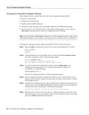
... system image in nonvolatile memory.) Step 4 Exit the configuration mode by rebooting the router. however, the new settings do not take effect only when the server restarts, for example, when you switch the power off and on a network server. (See Table B-3.) To change the configuration register while running the IOS software, follow : • Recover a lost password. • Change the console baud rate. • Enable or disable the Break function. • Manually boot the operating system using the b command...
... system image in nonvolatile memory.) Step 4 Exit the configuration mode by rebooting the router. however, the new settings do not take effect only when the server restarts, for example, when you switch the power off and on a network server. (See Table B-3.) To change the configuration register while running the IOS software, follow : • Recover a lost password. • Change the console baud rate. • Enable or disable the Break function. • Manually boot the operating system using the b command...
Hardware Maintenance Manual
Page 138
... tray layout 5-5 config-register value B-2 configuration command 3-22 configuration register B-1-B-6 boot field B-3 changing settings B-2 Cisco 4500-M D-4 Cisco 4700 D-4 displaying settings C-3 resetting C-3 confreg command D-4 connections 10BaseT 2-10 9-pin D-type 3-2 auxiliary port 2-9 considerations when making 2-10 console port 2-9 Ethernet attaching to network 3-3 port, considerations 2-12 final 3-22 NT1 3-6 optical bypass switch 3-13 power 3-22 preparing to make 2-7 serial 3-5 Token Ring 2-13, 3-2 console cable, pinout A-2 port alarm message 4-3 connections 2-9 console port RJ-45...
... tray layout 5-5 config-register value B-2 configuration command 3-22 configuration register B-1-B-6 boot field B-3 changing settings B-2 Cisco 4500-M D-4 Cisco 4700 D-4 displaying settings C-3 resetting C-3 confreg command D-4 connections 10BaseT 2-10 9-pin D-type 3-2 auxiliary port 2-9 considerations when making 2-10 console port 2-9 Ethernet attaching to network 3-3 port, considerations 2-12 final 3-22 NT1 3-6 optical bypass switch 3-13 power 3-22 preparing to make 2-7 serial 3-5 Token Ring 2-13, 3-2 console cable, pinout A-2 port alarm message 4-3 connections 2-9 console port RJ-45...

Hardware Maintenance Manual
Page 141
... P packing list 2-36 pinouts auxiliary port A-2 BRI 3-8, A-22 console port A-2 EIA/TIA-232 dual-port A-4 four-port A-5 EIA/TIA-449 dual-port A-7 four-port A-8 EIA-530 dual-port A-16 four-port A-18 EIA-TIA-232, four-port A-5 Ethernet (AUI) A-19 RJ-45 A-20 serial cable A-3-A-18 Token Ring A-21 V.35 dual-port A-10 four-port A-11 X.21 dual-port A-14 four-port A-15 polarity, Ethernet LED 4-5 port locations 2-7 software configuration, serial 4-8 power LED indication 3-22 light 4-3 specifications 1-3 supply features 2-4 system, troubleshooting 4-2 preparing for installation 2-1 to make connections...
... P packing list 2-36 pinouts auxiliary port A-2 BRI 3-8, A-22 console port A-2 EIA/TIA-232 dual-port A-4 four-port A-5 EIA/TIA-449 dual-port A-7 four-port A-8 EIA-530 dual-port A-16 four-port A-18 EIA-TIA-232, four-port A-5 Ethernet (AUI) A-19 RJ-45 A-20 serial cable A-3-A-18 Token Ring A-21 V.35 dual-port A-10 four-port A-11 X.21 dual-port A-14 four-port A-15 polarity, Ethernet LED 4-5 port locations 2-7 software configuration, serial 4-8 power LED indication 3-22 light 4-3 specifications 1-3 supply features 2-4 system, troubleshooting 4-2 preparing for installation 2-1 to make connections...


