Cisco WS-X401310GE-RF - Supervisor Engine II-Plus-10GE Support and Manuals
Get Help and Manuals for this Cisco item
View All Support Options Below
Free Cisco WS-X401310GE-RF manuals!
Problems with Cisco WS-X401310GE-RF?
Ask a Question
Free Cisco WS-X401310GE-RF manuals!
Problems with Cisco WS-X401310GE-RF?
Ask a Question
Popular Cisco WS-X401310GE-RF Manual Pages
Hardware Maintenance Manual - Page 3

... OF THIS LICENSE. Customer agrees to Software which the error occurred. Customer agrees that a license fee was paid and the other trademarks, service marks, registered trademarks, or registered service marks mentioned in this manual is subject to restrictions as authorized by Cisco, (2) has not been installed, operated, repaired, or maintained in accordance with respect to nonconforming...
Hardware Maintenance Manual - Page 4

...warranty does not apply to the Cisco Service Partner if the Hardware was exported pursuant to the multinational uplift program as soon as appropriate) will supply replacement parts for shipment of advance replacements to Customer, for a period of destination without problems or interruptions. Restricted Rights - Cisco's software and supporting documentation are provided with respect to...
Hardware Maintenance Manual - Page 9

... 2-28 Figure 2-29 Figure 2-30 Figure 2-31 Figure 2-32
Cisco 4000 Series Chassis-Front Panel 1-2 Cisco 4000 Series Memory Systems and Software Images 1-4 Installation Checklist 2-5 Router-Rear View Showing Slot Numbering and Interface Ports 2-7 Router-Rear View Showing Serial Port Unit Numbering 2-8 Slot Filler Panel 2-9 Ethernet Network Processor Module with AUI and 10BaseT Connectors 2-11 Single...
Hardware Maintenance Manual - Page 15

... of product information. UniverCD is updated and shipped monthly, so it may be familiar with a DC-input power supply. To order UniverCD, contact your warranty package.
Document Objectives
This publication contains the initial site preparation, installation, troubleshooting, and selected upgrade and maintenance procedures. All Cisco technical documentation and additional literature...
Hardware Maintenance Manual - Page 16

...Router," includes instructions for opening the
chassis, replacing or adding network processor modules, and replacing single in-line memory modules (SIMMs).
• Appendix A, "Cabling Specifications," provides cable illustrations, cable pinouts, and signal
descriptions for the console and auxiliary ports, synchronous serial cables, and Ethernet (AUI) cables.
• Appendix B, "Cisco 4000 Series...
Hardware Maintenance Manual - Page 28

... Hardware Installation and Maintenance Intermittent problems
-
Additional network processor modules
- Removal or replacement of all actions relevant to the router. Make entries as additional equipment, and most provide either a V.35, EIA/TIA-449, or EIA-530 electrical interface.
• Ethernet transceiver. • Token Ring media attachment unit (MAU). • Optical bypass switch or...
Hardware Maintenance Manual - Page 37

...for Installation 2-15 For instance, the recommended maximum rate for each serial interface ...
256
78
102
31
50
15
Balanced drivers allow EIA/TIA-449 signals to travel ...problems that might arise and can compensate for them, you can get good results at signal speeds up your own risk. EIA/TIA-232 Connections
EIA/TIA-232, the most common interface standard in the United States, supports...
Hardware Maintenance Manual - Page 43

...-timing was previously entered in the configuration file, then dte-invert-timing must be manually changed. Nine different serial cables are not interchangeable. An error message will be configured with the system. This cable, available from your customer service representative, is not configured. Preparing for NRZI, move the jumpers to the position shown...
Hardware Maintenance Manual - Page 49
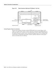
... in making your network connections will prevent the FDDI interface from the PHY-A XMTR port. Network Connection Considerations
Figure 2-27
Dual-Attachment Multimode FDDI Module-End View LEDs (2)
PHY-B Multimode ports
PHY-A
PHY-B PHY-A
PHY-B RING OP
FDDI
OPT-BYPASS
PHY-A RING OP
Optical bypass switch connector
H1400a
Alignment groove
Mounting screw locations
Alignment groove
The...
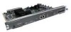
Hardware Maintenance Manual - Page 50
... Installation and Maintenance In addition, the system software can enable the optical bypass switch if a problem is a passive optical device powered by the FDDI module. If a fault in the router occurs, or if power is lost, the optical bypass switch is lost. Network Connection Considerations
Figure 2-29
Single-Attachment Multimode FDDI Module-End View LED
PHY...
Hardware Maintenance Manual - Page 54

.... The figure shows the cable impedance set to a channel service unit (CSU).
Figure 2-35 also shows the location of 2.048 Mbps. These jumpers set jumper J2 as a serial interface that supports ISDN PRI. The CE1, shown in the G.703 specification. To set capacitive coupling between the transmit (Tx) shield and chassis ground, set the cable impedance to 24 virtual...
Hardware Maintenance Manual - Page 67

... connection (other terminals should be made to a BRI module properly installed within the host chassis. Damage to the equipment and injury to timing slips. This is fully transportable between the ISDN ports used. The BRI network processor module is accommodated for each compatible chassis has no other than by a nonremovable, connect one -time-only...
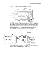
Hardware Maintenance Manual - Page 70
... this chapter.
3-12 Cisco 4000 Series Hardware Installation and Maintenance
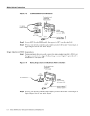
Making Network Connections
Figure 3-10
Dual-Attachment FDDI Connections
Dual attachment multimode FDDI module
To optical bypass switch
PHY-A (to PHY-B)
PHY-B PHY-A
RING OP
FDDI
OPT-BYPASS
RING OP
PHY-B (to PHY-A)
PHY-B PHY-A
Optical bypass switch connector (DIN)
Optical bypass interface cable
H1573a
Step...
Hardware Maintenance Manual - Page 127

... console each time you isolate or rule out hardware problems encountered when installing your router. If you set the software configuration register (bits 3, 2, 1, and 0) to zero, you can break to the ROM monitor prompt. The Cisco 4500-M and Cisco 4700 ROM monitor supports more features than the familiar Cisco 4000-M ROM monitor.
The ROM Monitor can start...
Hardware Maintenance Manual - Page 141

...V.35 dual-port A-10 four-port A-11 X.21 dual-port A-14 four-port A-15 polarity, Ethernet LED 4-5 port locations 2-7 software configuration, serial 4-8 power LED indication 3-22 light 4-3 specifications 1-3 supply features 2-4 system, troubleshooting 4-2 preparing for installation 2-1 to make connections 2-7 preventing ESD damage 2-3 preventive site configuration 2-4 printing summary of ROM monitor...
Cisco WS-X401310GE-RF Reviews
We have not received any reviews for Cisco yet.