
Hardware Installation Guide
Page 11
...and Adapter Pinouts B-9 Identifying a Crossover Cable B-9 Adapter Pinouts B-10 Managing the Switch by Using the Cluster Management Suite C-1 Connecting to an Ethernet Port C-2 Launching the Switch Home Page C-3 CMS Requirements C-5 Recommended Configuration for Web-Based Management C-6 Operating System and Browser Support C-6 Supported Java Plug-Ins C-7 Java Plug-In Notes C-8 Where to Go Next C-8 Quick Setup By Using the CLI-Based Setup Program D-1 Methods for Accessing the CLI D-2 Accessing the CLI Through Express Setup (Unconfigured Switch Only) D-2 Accessing the CLI Through the Console Port...
...and Adapter Pinouts B-9 Identifying a Crossover Cable B-9 Adapter Pinouts B-10 Managing the Switch by Using the Cluster Management Suite C-1 Connecting to an Ethernet Port C-2 Launching the Switch Home Page C-3 CMS Requirements C-5 Recommended Configuration for Web-Based Management C-6 Operating System and Browser Support C-6 Supported Java Plug-Ins C-7 Java Plug-In Notes C-8 Where to Go Next C-8 Quick Setup By Using the CLI-Based Setup Program D-1 Methods for Accessing the CLI D-2 Accessing the CLI Through Express Setup (Unconfigured Switch Only) D-2 Accessing the CLI Through the Console Port...

Hardware Installation Guide
Page 32
... MASTR LED is also green on a single switch or on page 4-2. The IP address is started should receive a DHCP address from the switch. To create a username for the switch, use to local routers and the Internet. The switch acts as a DHCP server during the Express Setup procedure, and only the PC or workstation connected to configure a switch. After the switch powers on, it begins the power-on self-test (POST), a series of the power cable to the switch. You...
... MASTR LED is also green on a single switch or on page 4-2. The IP address is started should receive a DHCP address from the switch. To create a username for the switch, use to local routers and the Internet. The switch acts as a DHCP server during the Express Setup procedure, and only the PC or workstation connected to configure a switch. After the switch powers on, it begins the power-on self-test (POST), a series of the power cable to the switch. You...

Hardware Installation Guide
Page 36
... enabled, the switch detects the required cable type for connections to enable the automatic crossover feature. Therefore, you can use either a crossover or a straight-through Ethernet cable between an Ethernet port of the switch and the Ethernet port of the connection. For configuration information for instructions on the switch and PC or workstation. To configure the switch by using the command-line interface (CLI)-based setup program, see Appendix D, "Quick Setup By Using the CLI-Based Setup Program." Starting Express Setup Chapter 1 Using Express Setup...
... enabled, the switch detects the required cable type for connections to enable the automatic crossover feature. Therefore, you can use either a crossover or a straight-through Ethernet cable between an Ethernet port of the switch and the Ethernet port of the connection. For configuration information for instructions on the switch and PC or workstation. To configure the switch by using the command-line interface (CLI)-based setup program, see Appendix D, "Quick Setup By Using the CLI-Based Setup Program." Starting Express Setup Chapter 1 Using Express Setup...
Hardware Installation Guide
Page 37
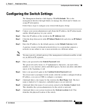
... 1 Using Express Setup Configuring the Switch Settings Configuring the Switch Settings The Management Interface field displays VLAN1-Default. Enter the IP address of the switch. 78-15136-02 Catalyst 3750 Switch Hardware Installation Guide 1-9 This identifies the physical location of the switch in the Switch Password field. Enter the IP address for the default gateway in the IP Subnet Mask field, and select an IP Subnet Mask. The host name is configured with an IP address...
... 1 Using Express Setup Configuring the Switch Settings Configuring the Switch Settings The Management Interface field displays VLAN1-Default. Enter the IP address of the switch. 78-15136-02 Catalyst 3750 Switch Hardware Installation Guide 1-9 This identifies the physical location of the switch in the Switch Password field. Enter the IP address for the default gateway in the IP Subnet Mask field, and select an IP Subnet Mask. The host name is configured with an IP address...
Hardware Installation Guide
Page 38
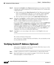
... going to use Telnet to manage the switch by using the CLI. Click Save to save your settings. b. Enable SNMP only if you plan to manage switches by using Cisco Works or another SNMP-based network-management system. Enter the Telnet password again in the Confirm Telnet Password field. (Optional) Click Enable to clear your settings to the switch, or click Cancel to configure Simple Network Management Protocol (SNMP). If you set the SNMP write community, users can install the switch in your switch (for example: 172...
... going to use Telnet to manage the switch by using the CLI. Click Save to save your settings. b. Enable SNMP only if you plan to manage switches by using Cisco Works or another SNMP-based network-management system. Enter the Telnet password again in the Confirm Telnet Password field. (Optional) Click Enable to clear your settings to the switch, or click Cancel to configure Simple Network Management Protocol (SNMP). If you set the SNMP write community, users can install the switch in your switch (for example: 172...
Hardware Installation Guide
Page 40
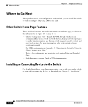
... to gather link information, and display switch images to the switch, see Appendix C, "Managing the Switch by using CMS or the CLI. For more information, refer to the switch software configuration guide For CMS requirements, see Chapter 3, "Installation." 1-12 Catalyst 3750 Switch Hardware Installation Guide 78-15136-02 Other Switch Home Page Features These additional features are available from the switch home page, as Telnet and Extended Ping. • Help Resources-Access Catalyst 3750 documentation.
... to gather link information, and display switch images to the switch, see Appendix C, "Managing the Switch by using CMS or the CLI. For more information, refer to the switch software configuration guide For CMS requirements, see Chapter 3, "Installation." 1-12 Catalyst 3750 Switch Hardware Installation Guide 78-15136-02 Other Switch Home Page Features These additional features are available from the switch home page, as Telnet and Extended Ping. • Help Resources-Access Catalyst 3750 documentation.

Hardware Installation Guide
Page 46
...). Therefore, you can use the mdix auto command in Appendix B, "Connector and Cable Specifications." You can use a crossover cable. Catalyst 3750 Switch Hardware Installation Guide 2-6 78-15136-02 If the connected device also supports autonegotiation, the switch port negotiates the best connection (that is, the fastest line speed that the cable is enabled, the switch detects the required cable type for autonegotiation, the port senses the speed and duplex settings of device on the switch to switches or hubs, use Category 3 or...
...). Therefore, you can use the mdix auto command in Appendix B, "Connector and Cable Specifications." You can use a crossover cable. Catalyst 3750 Switch Hardware Installation Guide 2-6 78-15136-02 If the connected device also supports autonegotiation, the switch port negotiates the best connection (that is, the fastest line speed that the cable is enabled, the switch detects the required cable type for autonegotiation, the port senses the speed and duplex settings of device on the switch to switches or hubs, use Category 3 or...

Hardware Installation Guide
Page 49
... power and is not powered on. Table 2-1 System LED Color Off Green Amber System Status System is functioning properly. Table 2-2 RPS LED Color Off Green Flashing green Amber Flashing amber RPS Status RPS is connected and ready to this device). 78-15136-02 Catalyst 3750 Switch Hardware Installation Guide 2-9 If it is unavailable because it does not, the RPS fan could have failed. RPS is off or not properly connected. RPS LED The RPS LED shows the RPS status...
... power and is not powered on. Table 2-1 System LED Color Off Green Amber System Status System is functioning properly. Table 2-2 RPS LED Color Off Green Flashing green Amber Flashing amber RPS Status RPS is connected and ready to this device). 78-15136-02 Catalyst 3750 Switch Hardware Installation Guide 2-9 If it is unavailable because it does not, the RPS fan could have failed. RPS is off or not properly connected. RPS LED The RPS LED shows the RPS status...
Hardware Installation Guide
Page 58
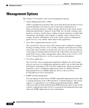
... access the CLI either by connecting your management station directly to the switch console port or by using Telnet from a SNMP-compatible management station that came with your network through a web browser such as HP OpenView or SunNet Manager. Refer to the CiscoView documentation for more information. 2-18 Catalyst 3750 Switch Hardware Installation Guide 78-15136-02 Refer to the switch software configuration guide on Cisco.com, and the online help for more information. • SNMP network management You can manage switches...
... access the CLI either by connecting your management station directly to the switch console port or by using Telnet from a SNMP-compatible management station that came with your network through a web browser such as HP OpenView or SunNet Manager. Refer to the CiscoView documentation for more information. 2-18 Catalyst 3750 Switch Hardware Installation Guide 78-15136-02 Refer to the switch software configuration guide on Cisco.com, and the online help for more information. • SNMP network management You can manage switches...

Hardware Installation Guide
Page 90
... the cable guide to the Console Port" section on page 1-4 and the "Starting the Terminal Emulation Software" section on page 1-6. • Power on page 3-37. • Connect to the switch software configuration guide or the switch command reference. See the "Completing the Setup Program" section on page D-11. • Connect to the "Accessing the Switch from obscuring the front panel of the switch and the other devices installed in the rack. To use the CLI, enter commands...
... the cable guide to the Console Port" section on page 1-4 and the "Starting the Terminal Emulation Software" section on page 1-6. • Power on page 3-37. • Connect to the switch software configuration guide or the switch command reference. See the "Completing the Setup Program" section on page D-11. • Connect to the "Accessing the Switch from obscuring the front panel of the switch and the other devices installed in the rack. To use the CLI, enter commands...

Hardware Installation Guide
Page 96
... and the "Connecting to an SFP Module" section on page 3-37. • Connect to a Power Source" section on the table or shelf near an AC power source. To use the CLI, enter commands at the Switch> prompt through the console port by using a terminal program or through the network by using Telnet. See the "Connecting StackWise Cable to StackWise Ports" section on page 3-46 to install the switch on a table or shelf: Step...
... and the "Connecting to an SFP Module" section on page 3-37. • Connect to a Power Source" section on the table or shelf near an AC power source. To use the CLI, enter commands at the Switch> prompt through the console port by using a terminal program or through the network by using Telnet. See the "Connecting StackWise Cable to StackWise Ports" section on page 3-46 to install the switch on a table or shelf: Step...

Hardware Installation Guide
Page 105
... default. If the port LED does not turn on, the device at the other end of device on the other end of the connection. Step 1 When connecting to workstations, servers, routers, and Cisco IP Phones, connect a straight-through cable for copper Ethernet connections and configures the interfaces accordingly. Step 2 Connect the other end 78-15136-02 Catalyst 3750 Switch Hardware Installation Guide 3-45 The port LED turns on the switch, regardless the type of the cable to the switch software configuration guide or the switch command reference...
... default. If the port LED does not turn on, the device at the other end of device on the other end of the connection. Step 1 When connecting to workstations, servers, routers, and Cisco IP Phones, connect a straight-through cable for copper Ethernet connections and configures the interfaces accordingly. Step 2 Connect the other end 78-15136-02 Catalyst 3750 Switch Hardware Installation Guide 3-45 The port LED turns on the switch, regardless the type of the cable to the switch software configuration guide or the switch command reference...

Hardware Installation Guide
Page 111
...LEDs turn amber for 2 seconds. 78-15136-02 Catalyst 3750 Switch Hardware Installation Guide 4-1 You can also get statistics from the browser interface, from the command-line interface (CLI), or from a Simple Network Management Protocol (SNMP) workstation. For a full description of tests that run automatically to the software configuration guide, the switch command reference guide on page 2-8. This chapter describes these topics for troubleshooting problems: • Understanding POST Results, page 4-1 • Clearing the Switch IP Address and Configuration, page 4-2 • Replacing...
...LEDs turn amber for 2 seconds. 78-15136-02 Catalyst 3750 Switch Hardware Installation Guide 4-1 You can also get statistics from the browser interface, from the command-line interface (CLI), or from a Simple Network Management Protocol (SNMP) workstation. For a full description of tests that run automatically to the software configuration guide, the switch command reference guide on page 2-8. This chapter describes these topics for troubleshooting problems: • Understanding POST Results, page 4-1 • Clearing the Switch IP Address and Configuration, page 4-2 • Replacing...

Hardware Installation Guide
Page 125
... can use the mdix auto command in the CLI to enable the automatic crossover feature. For configuration information for this feature, refer to other end of the connection. Figure B-1 shows the pinout. Connector Specifications These sections describe the connectors used with the Catalyst 3750 switches. 10/100/1000 Ports The 10/100/1000 Ethernet ports on the other devices. When the automatic crossover feature is disabled by default. The...
... can use the mdix auto command in the CLI to enable the automatic crossover feature. For configuration information for this feature, refer to other end of the connection. Figure B-1 shows the pinout. Connector Specifications These sections describe the connectors used with the Catalyst 3750 switches. 10/100/1000 Ports The 10/100/1000 Ethernet ports on the other devices. When the automatic crossover feature is disabled by default. The...
Hardware Installation Guide
Page 143
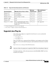
... for the OS and Motif library patch 103461-24 Not supported 1. On Solaris platforms, follow the instructions in the README_FIRST.txt file to access and run the Java-based CMS: • Java plug-in 1.4 • Java plug-in 1.3.1 These Java plug-ins are supported both in . 78-15136-02 Catalyst 3750 Switch Hardware Installation Guide C-7 Service Pack 1 or higher is not...
... for the OS and Motif library patch 103461-24 Not supported 1. On Solaris platforms, follow the instructions in the README_FIRST.txt file to access and run the Java-based CMS: • Java plug-in 1.4 • Java plug-in 1.3.1 These Java plug-ins are supported both in . 78-15136-02 Catalyst 3750 Switch Hardware Installation Guide C-7 Service Pack 1 or higher is not...
Hardware Installation Guide
Page 144
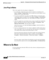
... the version number in the Control Panel menu. • If you are enabled. • If you have installed and enabled the plug-in, open the Java Plug-in Control Panel (Start > Programs > Java Plug-in Control Panel), and verify these settings: In the Proxies tab, verify that Use browser settings is enabled by selecting Start > Settings > Control Panel > Java Plug-in the Quick Enable menu, disable the options by selecting Start > Programs > Network Associates > Virus Scan Console > Configure.
... the version number in the Control Panel menu. • If you are enabled. • If you have installed and enabled the plug-in, open the Java Plug-in Control Panel (Start > Programs > Java Plug-in Control Panel), and verify these settings: In the Proxies tab, verify that Use browser settings is enabled by selecting Start > Settings > Control Panel > Java Plug-in the Quick Enable menu, disable the options by selecting Start > Programs > Network Associates > Virus Scan Console > Configure.
Hardware Installation Guide
Page 147
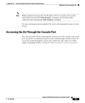
... command. To access the switch through a Telnet session. For more information about using the CLI, refer to the serial port on your PC or workstation and access the switch through the console port, follow the steps in Express Setup mode, the IP address 10.0.0.1 remains active on page D-4. 78-15136-02 Catalyst 3750 Switch Hardware Installation Guide D-3 Accessing the CLI Through the Console Port You can access the CLI by connecting the console port of this release. You lose the Telnet connection...
... command. To access the switch through a Telnet session. For more information about using the CLI, refer to the serial port on your PC or workstation and access the switch through the console port, follow the steps in Express Setup mode, the IP address 10.0.0.1 remains active on page D-4. 78-15136-02 Catalyst 3750 Switch Hardware Installation Guide D-3 Accessing the CLI Through the Console Port You can access the CLI by connecting the console port of this release. You lose the Telnet connection...
Hardware Installation Guide
Page 149
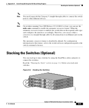
... disabled by using the StackWise cables and ports to connect the switches. For configuration information for all connections to an Ethernet port on page 3-12 before you can stack up to nine switches by default. Appendix D Quick Setup By Using the CLI-Based Setup Program Stacking the Switches (Optional) Note You need to provide the Category 5 straight-through cable for this feature, refer to the switch software configuration guide or the switch command reference. Note On switches running Cisco IOS...
... disabled by using the StackWise cables and ports to connect the switches. For configuration information for all connections to an Ethernet port on page 3-12 before you can stack up to nine switches by default. Appendix D Quick Setup By Using the CLI-Based Setup Program Stacking the Switches (Optional) Note You need to provide the Category 5 straight-through cable for this feature, refer to the switch software configuration guide or the switch command reference. Note On switches running Cisco IOS...
Hardware Installation Guide
Page 157
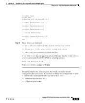
... this config. [2] Save this configuration or want to perform other management tasks, use it the next time the switch reboots, save the configuration and use one of these tools: • Command-line interface (CLI) • CMS from your selection, and press Return. If you want to nvram and exit. interface FastEthernet1/0/2 interface FastEthernet1/0/3 ! ... ! If you created. Enter your selection [2]:2 Make your browser 78-15136-02 Catalyst 3750 Switch Hardware Installation Guide...
... this config. [2] Save this configuration or want to perform other management tasks, use it the next time the switch reboots, save the configuration and use one of these tools: • Command-line interface (CLI) • CMS from your selection, and press Return. If you want to nvram and exit. interface FastEthernet1/0/2 interface FastEthernet1/0/3 ! ... ! If you created. Enter your selection [2]:2 Make your browser 78-15136-02 Catalyst 3750 Switch Hardware Installation Guide...
Hardware Installation Guide
Page 192
... and cables StackWise cables cable numbers 2-15 connecting to 3-37 cautions xvi chassis warning, rack-mounting and servicing E-19 Cisco IP Phones, connecting to 3-45 Cisco RPS See RPS CiscoView 2-18 CLI 2-18 accessing by using Express Setup D-2 accessing through console port D-3 Cluster Management Suite See CMS CMS 2-18 accessing your switch C-1 operating systems and supported browsers C-6 requirements C-5 to C-7 supported Java plug-ins C-7 command-line interface See CLI connecting to 10/100/1000 ports 3-44 to 10/100 ports 3-44 to console port 3-8, B-6 to SFP modules...
... and cables StackWise cables cable numbers 2-15 connecting to 3-37 cautions xvi chassis warning, rack-mounting and servicing E-19 Cisco IP Phones, connecting to 3-45 Cisco RPS See RPS CiscoView 2-18 CLI 2-18 accessing by using Express Setup D-2 accessing through console port D-3 Cluster Management Suite See CMS CMS 2-18 accessing your switch C-1 operating systems and supported browsers C-6 requirements C-5 to C-7 supported Java plug-ins C-7 command-line interface See CLI connecting to 10/100/1000 ports 3-44 to 10/100 ports 3-44 to console port 3-8, B-6 to SFP modules...


