

Installation Guide
Page 6
... Configuration 1-33 Installing and Starting Up the Switch 2-1 Preparing for Using the Switch 1-25 Small- Contents 2 C H A P T E R LEDs 1-11 System LED 1-14 RPS LED 1-15 Port LEDs and Modes 1-16 Rear-Panel Description 1-21 Power Connectors 1-22 Internal Power Supply Connector 1-23 Cisco RPS Connector 1-23 Console Port 1-24 Management Options 1-24 Network Configuration Examples 1-25 Design Concepts...
... Configuration 1-33 Installing and Starting Up the Switch 2-1 Preparing for Using the Switch 1-25 Small- Contents 2 C H A P T E R LEDs 1-11 System LED 1-14 RPS LED 1-15 Port LEDs and Modes 1-16 Rear-Panel Description 1-21 Power Connectors 1-22 Internal Power Supply Connector 1-23 Cisco RPS Connector 1-23 Console Port 1-24 Management Options 1-24 Network Configuration Examples 1-25 Design Concepts...

Installation Guide
Page 7
... Connecting to a GigaStack GBIC Module Port 2-22 Connecting a PC or Terminal to the Console Port 2-23 Assigning Switch Information 2-24 Using the Setup Program 2-25 Using BOOTP 2-29 Default Configuration Settings 2-29 Where to Go Next 2-31 Troubleshooting 3-1 Understanding POST Results 3-2 Diagnosing Problems 3-3 Contents 78-6456-03 Catalyst 3500 Series XL Hardware Installation Guide vii
... Connecting to a GigaStack GBIC Module Port 2-22 Connecting a PC or Terminal to the Console Port 2-23 Assigning Switch Information 2-24 Using the Setup Program 2-25 Using BOOTP 2-29 Default Configuration Settings 2-29 Where to Go Next 2-31 Troubleshooting 3-1 Understanding POST Results 3-2 Diagnosing Problems 3-3 Contents 78-6456-03 Catalyst 3500 Series XL Hardware Installation Guide vii

Installation Guide
Page 26
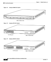
... 13 14 13X 15 16 17 18 19 20 21 22 23 24 SYSTEM MODE RPS STATUS 2X DUPLX SPEED LINE PWR 12X 14X 23X ...XL Switches Switch Description WS-C3508G-XL 8 GBIC1-based gigabit module slots 1 SYSTEM 2 3 RPS 4 5 MODE STATUS UTIL DUPLX SPEED 6 7 8 WS-C3512-XL 12 autosensing10/100 Ethernet ports 2 GBIC-based gigabit module slots WS-C3524-XL 24 autosensing 10/100 Ethernet ports 2 fixed GBIC-based gigabit module slots WS-C3524-PWR-XL 24 autosensing 10/100 inline-power Ethernet ports 2 GBIC-based gigabit module slots WS-C3548-XL 48 autosensing 10/100 Ethernet ports...
... 13 14 13X 15 16 17 18 19 20 21 22 23 24 SYSTEM MODE RPS STATUS 2X DUPLX SPEED LINE PWR 12X 14X 23X ...XL Switches Switch Description WS-C3508G-XL 8 GBIC1-based gigabit module slots 1 SYSTEM 2 3 RPS 4 5 MODE STATUS UTIL DUPLX SPEED 6 7 8 WS-C3512-XL 12 autosensing10/100 Ethernet ports 2 GBIC-based gigabit module slots WS-C3524-XL 24 autosensing 10/100 Ethernet ports 2 fixed GBIC-based gigabit module slots WS-C3524-PWR-XL 24 autosensing 10/100 inline-power Ethernet ports 2 GBIC-based gigabit module slots WS-C3548-XL 48 autosensing 10/100 Ethernet ports...

Installation Guide
Page 28
...PWR, and 3548 XL Features Feature Performance and Configuration Description • Autonegotiation of speed and duplex operation on 10/100 Ethernet ports • 12, 24, or 48 10/100 Ethernet ports and 2 GBIC-based Gigabit Ethernet slots • Support for up to 250 port-based VLANs •... ISL and IEEE 802.1Q trunking support on all ports • Support for voice VLAN ID (VVID) • High-speed EtherChannel connections between switches...
...PWR, and 3548 XL Features Feature Performance and Configuration Description • Autonegotiation of speed and duplex operation on 10/100 Ethernet ports • 12, 24, or 48 10/100 Ethernet ports and 2 GBIC-based Gigabit Ethernet slots • Support for up to 250 port-based VLANs •... ISL and IEEE 802.1Q trunking support on all ports • Support for voice VLAN ID (VVID) • High-speed EtherChannel connections between switches...

Installation Guide
Page 29
...operates on AC input and supplies DC output to the Catalyst 3524-PWR XL switch Inline Power (Catalyst 3524-PWR XL switch only) • Ability to the Catalyst 3512, 3524, and 3548 XL switches • Connection for optional Cisco RPS 300 that you press.) These front-panel components are described in ...output to provide inline power for Cisco IP Phones from all 24 10/100 Ethernet ports • Auto-detection and control of inline phone power on a per-port basis on all 10/100 ports • Support for fan-fault and over-temperature detection through Visual Switch Manager (VSM) Front-Panel ...
...operates on AC input and supplies DC output to the Catalyst 3524-PWR XL switch Inline Power (Catalyst 3524-PWR XL switch only) • Ability to the Catalyst 3512, 3524, and 3548 XL switches • Connection for optional Cisco RPS 300 that you press.) These front-panel components are described in ...output to provide inline power for Cisco IP Phones from all 24 10/100 Ethernet ports • Auto-detection and control of inline phone power on a per-port basis on all 10/100 ports • Support for fan-fault and over-temperature detection through Visual Switch Manager (VSM) Front-Panel ...
Installation Guide
Page 30
... 1X 34 56 78 SYSTEM MODE RPS 2X STATUS UTIL DUPLX SPEED 9 10 11 12 11X 12X 10/100 ports Figure 1-4 Catalyst 3524 XL Switch 1 2 GBIC module slots 12 1X 34 56 78 MODE SYSTEM RPS STATUS 2X UTIL DUPLX SPEED 9 10 11 12 11X 12X 13 14 13X 15 ...16 17 18 19 20 21 22 23 24 23X 14X 24X 10/100 ports 1 2 GBIC module slots Catalyst 3500 Series XL Hardware Installation Guide 1-6 26237...
... 1X 34 56 78 SYSTEM MODE RPS 2X STATUS UTIL DUPLX SPEED 9 10 11 12 11X 12X 10/100 ports Figure 1-4 Catalyst 3524 XL Switch 1 2 GBIC module slots 12 1X 34 56 78 MODE SYSTEM RPS STATUS 2X UTIL DUPLX SPEED 9 10 11 12 11X 12X 13 14 13X 15 ...16 17 18 19 20 21 22 23 24 23X 14X 24X 10/100 ports 1 2 GBIC module slots Catalyst 3500 Series XL Hardware Installation Guide 1-6 26237...

Installation Guide
Page 31
... SPEED LINE PWR 9 10 11 12 11X 12X 13 14 13X 15 16 17 18 19 20 21 22 23 24 23X 14X 24X 10/100 inline-power ports Figure 1-6 Catalyst 3548 XL Switch 1 2 GBIC module slots 28010 SYSTEM RPS 12 1X 34 56 78 9 10 11 12 13 14 15 16 15X 17... SPEED 2X 47X 1 MODE 16X 18X 32X 34X 2 48X 10/100 ports GBIC module slots 10/100 Ports The 10/100 ports on . The 10/100 switch ports can connect, up to any compatible network device: • 10BaseT-compatible devices such as workstations, Cisco IP Phones, and hubs through standard RJ-45 connectors and Category 3, 4, or...
... SPEED LINE PWR 9 10 11 12 11X 12X 13 14 13X 15 16 17 18 19 20 21 22 23 24 23X 14X 24X 10/100 inline-power ports Figure 1-6 Catalyst 3548 XL Switch 1 2 GBIC module slots 28010 SYSTEM RPS 12 1X 34 56 78 9 10 11 12 13 14 15 16 15X 17... SPEED 2X 47X 1 MODE 16X 18X 32X 34X 2 48X 10/100 ports GBIC module slots 10/100 Ports The 10/100 ports on . The 10/100 switch ports can connect, up to any compatible network device: • 10BaseT-compatible devices such as workstations, Cisco IP Phones, and hubs through standard RJ-45 connectors and Category 3, 4, or...
Installation Guide
Page 44
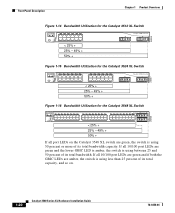
... more of its total bandwidth. If all 10/100 port LEDs are green and the lower GBIC LED is amber, the switch is using between 25 and 50 percent of its total capacity, and so on the Catalyst 3548 XL switch are amber, the switch is using less than 25 percent of its total bandwidth... 13 14 15 16 13X 17 18 19 20 21 22 23 24 15X 14X 16X < 25% + 25% - 49% + 50% + Catalyst 3500 XL 1 2 Figure 1-16 Bandwidth Utilization for the Catalyst 3548 XL Switch 28366 SYSTEM RPS STATUS UTIL DUPLX SPEED MODE 12 1X 3 24 56 78 9 10 11 12 13 14 15 16 15X 17...
... more of its total bandwidth. If all 10/100 port LEDs are green and the lower GBIC LED is amber, the switch is using between 25 and 50 percent of its total capacity, and so on the Catalyst 3548 XL switch are amber, the switch is using less than 25 percent of its total bandwidth... 13 14 15 16 13X 17 18 19 20 21 22 23 24 15X 14X 16X < 25% + 25% - 49% + 50% + Catalyst 3500 XL 1 2 Figure 1-16 Bandwidth Utilization for the Catalyst 3548 XL Switch 28366 SYSTEM RPS STATUS UTIL DUPLX SPEED MODE 12 1X 3 24 56 78 9 10 11 12 13 14 15 16 15X 17...

Installation Guide
Page 48
...-DSBUASYN=) containing that you want to connect the switch console port to the affected switch. It provides a fully-redundant power source for these applications. 1-24 Catalyst 3500 Series XL Hardware Installation Guide 78-6456-04 Management Options Chapter 1 Product Overview RPS Connector on the Catalyst 3524-PWR XL Switch The Cisco RPS 300 (model PWR300-AC-RPS) has...
...-DSBUASYN=) containing that you want to connect the switch console port to the affected switch. It provides a fully-redundant power source for these applications. 1-24 Catalyst 3500 Series XL Hardware Installation Guide 78-6456-04 Management Options Chapter 1 Product Overview RPS Connector on the Catalyst 3524-PWR XL Switch The Cisco RPS 300 (model PWR300-AC-RPS) has...
Installation Guide
Page 82
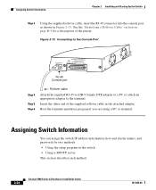
... CONSOLE DC INPUTS FOR REMOTE POWER SUPPLY SPECIFIED IN MANUAL. +5V @24A, +12V @1.0A RJ-45 Console port Step 4 Step 5 Step 6 Rollover cable Attach the supplied RJ-45-to-DB-9 female DTE adapter to a PC or attach an appropriate adapter to ... section on page B-5 for a description of the supplied rollover cable in the switch • Using a BOOTP server This section describes each method. 2-24 Catalyst 3500 Series XL Hardware Installation Guide 78-6456-04 Assigning Switch Information You can assign the switch IP address information, host and cluster names, and passwords by two methods: &#...
... CONSOLE DC INPUTS FOR REMOTE POWER SUPPLY SPECIFIED IN MANUAL. +5V @24A, +12V @1.0A RJ-45 Console port Step 4 Step 5 Step 6 Rollover cable Attach the supplied RJ-45-to-DB-9 female DTE adapter to a PC or attach an appropriate adapter to ... section on page B-5 for a description of the supplied rollover cable in the switch • Using a BOOTP server This section describes each method. 2-24 Catalyst 3500 Series XL Hardware Installation Guide 78-6456-04 Assigning Switch Information You can assign the switch IP address information, host and cluster names, and passwords by two methods: &#...
Installation Guide
Page 153
... to 2-18 described 1-7 groupings 1-7 illustrated 1-5 1000BaseX ports 1-9 cable lengths 2-7 connecting to 2-20 to 2-23 connectors and cables B-2 to B-3 GigaStack GBIC ports B-3 pinouts B-4 See also connectors and cables cautions xiii CGMP 1-3 Catalyst 3500 Series XL Hardware Installation Guide IN-1 and 24-inch racks 2-9 A AC power connecting to 2-17 connector...) 1-25 autonegotiation 1-8 B bandwidth utilization 1-19, 1-20 BOOTP 2-29 brackets See mounting brackets C cable guide, attaching 2-13 cable lengths 2-7 cabling 10/100 ports B-1 to B-4 1000BaseX ports B-2 to B-3 illustrated 1-9 19-
... to 2-18 described 1-7 groupings 1-7 illustrated 1-5 1000BaseX ports 1-9 cable lengths 2-7 connecting to 2-20 to 2-23 connectors and cables B-2 to B-3 GigaStack GBIC ports B-3 pinouts B-4 See also connectors and cables cautions xiii CGMP 1-3 Catalyst 3500 Series XL Hardware Installation Guide IN-1 and 24-inch racks 2-9 A AC power connecting to 2-17 connector...) 1-25 autonegotiation 1-8 B bandwidth utilization 1-19, 1-20 BOOTP 2-29 brackets See mounting brackets C cable guide, attaching 2-13 cable lengths 2-7 cabling 10/100 ports B-1 to B-4 1000BaseX ports B-2 to B-3 illustrated 1-9 19-
Installation Guide
Page 154
... connecting to 2-17 LED 1-15 Cisco SoftPhone software 1-31 CiscoView 1-25 Cluster Builder application 1-24 Cluster Management Suite 1-24 Cluster Manager application 1-24 Cluster View application 1-24 command-line interface (CLI) 1-25 configuration, default values 2-30 configuration examples, network 1-25 connecting to 10/100 ports 2-18 to 1000BaseX ports 2-20 to console port 2-18, B-3 to GBICs 2-21 to...
... connecting to 2-17 LED 1-15 Cisco SoftPhone software 1-31 CiscoView 1-25 Cluster Builder application 1-24 Cluster Management Suite 1-24 Cluster Manager application 1-24 Cluster View application 1-24 command-line interface (CLI) 1-25 configuration, default values 2-30 configuration examples, network 1-25 connecting to 10/100 ports 2-18 to 1000BaseX ports 2-20 to console port 2-18, B-3 to GBICs 2-21 to...
Installation Guide
Page 156
Index IOS command-line interface 1-25 IP address procedures 2-24 IP setup 2-26 J jewelry removal warning C-10 L LAN-to-phone jack 2-19 LEDs Catalyst 3508G XL front panel 1-11 Catalyst 3512 and 3524 XL front panel 1-12 Catalyst 3548 XL front panel 1-14 color meanings 1-18 duplex 1-17, 1-18 half-duplex...17 port 1-16 to 1-20 POST results 2-17, 3-2 RPS 1-15 speed 1-17 STAT 1-16 status 1-18 system 1-14 UTL 1-16, 1-18 lightning activity warning C-30 line power See inline power M management features and defaults 2-30 Mode button 1-11, 1-16 Mode label (on Catalyst 3548 XL only) 1-16 models, switch 1-2...
Index IOS command-line interface 1-25 IP address procedures 2-24 IP setup 2-26 J jewelry removal warning C-10 L LAN-to-phone jack 2-19 LEDs Catalyst 3508G XL front panel 1-11 Catalyst 3512 and 3524 XL front panel 1-12 Catalyst 3548 XL front panel 1-14 color meanings 1-18 duplex 1-17, 1-18 half-duplex...17 port 1-16 to 1-20 POST results 2-17, 3-2 RPS 1-15 speed 1-17 STAT 1-16 status 1-18 system 1-14 UTL 1-16, 1-18 lightning activity warning C-30 line power See inline power M management features and defaults 2-30 Mode button 1-11, 1-16 Mode label (on Catalyst 3548 XL only) 1-16 models, switch 1-2...
Installation Guide
Page 157
...ports B-2 adapters B-5 to B-7 cable, straight-through and crossover B-4 console port B-5 to B-7 RJ-45-to-DB-25 terminal adapter B-7 RJ-45-to-DB-9 PC adapter B-6 RJ-45-to-DB-9 terminal adapter B-6 rollover cable B-5 to B-7 port LEDs 1-16 to 1-20 port... modes changing 1-11, 1-16 LEDs 1-16 See also Mode button ports 10/100 1-5 1000BaseX 1-9 See also...procedures connection 2-18 to 2-24 installation 2-7 to 2-17 IP address 2-24 product disposal warning C-31 PSTN 1-33 publications, related xviii Public Switched Telephone Network See PSTN Q ...
...ports B-2 adapters B-5 to B-7 cable, straight-through and crossover B-4 console port B-5 to B-7 RJ-45-to-DB-25 terminal adapter B-7 RJ-45-to-DB-9 PC adapter B-6 RJ-45-to-DB-9 terminal adapter B-6 rollover cable B-5 to B-7 port LEDs 1-16 to 1-20 port... modes changing 1-11, 1-16 LEDs 1-16 See also Mode button ports 10/100 1-5 1000BaseX 1-9 See also...procedures connection 2-18 to 2-24 installation 2-7 to 2-17 IP address 2-24 product disposal warning C-31 PSTN 1-33 publications, related xviii Public Switched Telephone Network See PSTN Q ...
Installation Guide
Page 158
...shelf-mounting 2-17 shock hazard warning C-41 slots See ports 1-9 SNMP network management platforms 1-3, 1-25 software by model 1-2 software switch management 1-24 specifications A-1 stacking the chassis warning C-13 standard edition software, switches running 1-2 startup powering on 2-17 straight-through cable ... the CLI 1-25 temperature operating A-1 warning C-16 terminal, connecting to switch 2-23 terminal emulation software 2-23 TN power warning C-19 translated warnings C-1 troubleshooting 3-1 to 3-5 U UTL LED 1-16, 1-17 IN-6 Catalyst 3500 Series XL Hardware Installation Guide 78-6456-04
...shelf-mounting 2-17 shock hazard warning C-41 slots See ports 1-9 SNMP network management platforms 1-3, 1-25 software by model 1-2 software switch management 1-24 specifications A-1 stacking the chassis warning C-13 standard edition software, switches running 1-2 startup powering on 2-17 straight-through cable ... the CLI 1-25 temperature operating A-1 warning C-16 terminal, connecting to switch 2-23 terminal emulation software 2-23 TN power warning C-19 translated warnings C-1 troubleshooting 3-1 to 3-5 U UTL LED 1-16, 1-17 IN-6 Catalyst 3500 Series XL Hardware Installation Guide 78-6456-04


