

Installation Guide
Page 6
... Up the Switch 2-1 Preparing for Using the Switch 1-25 Small- Contents 2 C H A P T E R LEDs 1-11 System LED 1-14 RPS LED 1-15 Port LEDs and Modes 1-16 Rear-Panel Description 1-21 Power Connectors 1-22 Internal Power Supply Connector 1-23 Cisco RPS Connector 1-23 Console Port 1-24 Management Options 1-24 Network Configuration Examples 1-25 Design Concepts for Installation 2-2 Warnings 2-2 EMC Regulatory Statements 2-5 U.S.A. 2-5 Taiwan 2-5 Japan 2-6 Korea 2-6 Hungary 2-7 Installation Guidelines 2-7 Verifying Package Contents 2-8 Catalyst 3500 Series XL Hardware Installation Guide vi 78...
... Up the Switch 2-1 Preparing for Using the Switch 1-25 Small- Contents 2 C H A P T E R LEDs 1-11 System LED 1-14 RPS LED 1-15 Port LEDs and Modes 1-16 Rear-Panel Description 1-21 Power Connectors 1-22 Internal Power Supply Connector 1-23 Cisco RPS Connector 1-23 Console Port 1-24 Management Options 1-24 Network Configuration Examples 1-25 Design Concepts for Installation 2-2 Warnings 2-2 EMC Regulatory Statements 2-5 U.S.A. 2-5 Taiwan 2-5 Japan 2-6 Korea 2-6 Hungary 2-7 Installation Guidelines 2-7 Verifying Package Contents 2-8 Catalyst 3500 Series XL Hardware Installation Guide vi 78...

Installation Guide
Page 12
... are in angle brackets (< >). Chapter 3, "Troubleshooting," describes how to the switch. Appendix A, "Technical Specifications," lists the physical and environmental specifications for installing a switch on a rack, wall, table, or shelf. Appendix B, "Connector and Cable Specifications," describes the connectors, cables, and adapters that can be installed suggest possible deployment strategies. It describes the switch ports, the standards they support, and the switch LEDs. Conventions This guide uses the following chapters: Chapter 1, "Product Overview...
... are in angle brackets (< >). Chapter 3, "Troubleshooting," describes how to the switch. Appendix A, "Technical Specifications," lists the physical and environmental specifications for installing a switch on a rack, wall, table, or shelf. Appendix B, "Connector and Cable Specifications," describes the connectors, cables, and adapters that can be installed suggest possible deployment strategies. It describes the switch ports, the standards they support, and the switch LEDs. Conventions This guide uses the following chapters: Chapter 1, "Product Overview...

Installation Guide
Page 25
... specific to the Catalyst 3524-PWR XL switch is its ability to provide inline power to Cisco IP Phones. (Phone adapters are stackable 10/100 Ethernet switches to the Catalyst 3524-PWR XL 10/100 switch ports.) Figure 1-1 shows the switch models in different network topologies Features The Catalyst 3500 series XL switches-also referred to as Catalyst 3500 XL switches-are not required when connecting to which you can be deployed as servers, routers, and other network...
... specific to the Catalyst 3524-PWR XL switch is its ability to provide inline power to Cisco IP Phones. (Phone adapters are stackable 10/100 Ethernet switches to the Catalyst 3524-PWR XL 10/100 switch ports.) Figure 1-1 shows the switch models in different network topologies Features The Catalyst 3500 series XL switches-also referred to as Catalyst 3500 XL switches-are not required when connecting to which you can be deployed as servers, routers, and other network...

Installation Guide
Page 27
...; Inter-Switch Link (ISL) and IEEE 802.1Q trunking support on all ports • IEEE 802.1p capable • High-speed EtherChannel connections between switches and servers • 8192 MAC addresses • Cisco Group Management Protocol (CGMP) to limit the flooding of IP multicast traffic • Broadcast storm control to the switch 78-6456-04 Catalyst 3500 Series XL Hardware Installation Guide 1-3 GigaStack GBIC module - 1000BaseSX GBIC module - 1000BaseLX/LH GBIC module - 1000BaseZX GBIC module (support for Cisco Gigabit Interface Converter (GBIC) modules -
...; Inter-Switch Link (ISL) and IEEE 802.1Q trunking support on all ports • IEEE 802.1p capable • High-speed EtherChannel connections between switches and servers • 8192 MAC addresses • Cisco Group Management Protocol (CGMP) to limit the flooding of IP multicast traffic • Broadcast storm control to the switch 78-6456-04 Catalyst 3500 Series XL Hardware Installation Guide 1-3 GigaStack GBIC module - 1000BaseSX GBIC module - 1000BaseLX/LH GBIC module - 1000BaseZX GBIC module (support for Cisco Gigabit Interface Converter (GBIC) modules -

Installation Guide
Page 28
...) • High-speed EtherChannel connections between switches and servers • 8192 MAC addresses • IEEE 802.1p capable • CGMP to limit the flooding of IP multicast traffic • Broadcast storm control to prevent performance degradation from broadcast storms • SPAN port monitoring on any port • Support for command switch redundancy • Support for Cisco GBIC modules - GigaStack GBIC - 1000BaseSX GBIC module - 1000BaseLX/LH GBIC module - 1000BaseZX GBIC module Catalyst 3500 Series XL Hardware Installation Guide 1-4 78-6456-04...
...) • High-speed EtherChannel connections between switches and servers • 8192 MAC addresses • IEEE 802.1p capable • CGMP to limit the flooding of IP multicast traffic • Broadcast storm control to prevent performance degradation from broadcast storms • SPAN port monitoring on any port • Support for command switch redundancy • Support for Cisco GBIC modules - GigaStack GBIC - 1000BaseSX GBIC module - 1000BaseLX/LH GBIC module - 1000BaseZX GBIC module Catalyst 3500 Series XL Hardware Installation Guide 1-4 78-6456-04...

Installation Guide
Page 29
... a set of LEDs and a Mode button. (The Catalyst 3548 XL switch has a Mode label that operates on AC input and supplies DC output to the Catalyst 3524-PWR XL switch Inline Power (Catalyst 3524-PWR XL switch only) • Ability to provide inline power for Cisco IP Phones from all 24 10/100 Ethernet ports • Auto-detection and control of inline phone power on a per-port basis on all 10/100 ports • Support for fan...
... a set of LEDs and a Mode button. (The Catalyst 3548 XL switch has a Mode label that operates on AC input and supplies DC output to the Catalyst 3524-PWR XL switch Inline Power (Catalyst 3524-PWR XL switch only) • Ability to provide inline power for Cisco IP Phones from all 24 10/100 Ethernet ports • Auto-detection and control of inline phone power on a per-port basis on all 10/100 ports • Support for fan...

Installation Guide
Page 32
... line speed that both devices support and full-duplex transmission, if the attached device supports it) and configures itself accordingly. These ports also can sense the speed and duplex settings of half duplex, full duplex, 10 Mbps, or 100 Mbps. When you can use a crossover cable. The 10/100 ports on a port, the port Catalyst 3500 Series XL Hardware Installation Guide 1-8 78-6456-04 Ports operating at 100 Mbps. When connecting the switch to workstations, servers, routers, and Cisco...
... line speed that both devices support and full-duplex transmission, if the attached device supports it) and configures itself accordingly. These ports also can sense the speed and duplex settings of half duplex, full duplex, 10 Mbps, or 100 Mbps. When you can use a crossover cable. The 10/100 ports on a port, the port Catalyst 3500 Series XL Hardware Installation Guide 1-8 78-6456-04 Ports operating at 100 Mbps. When connecting the switch to workstations, servers, routers, and Cisco...

Installation Guide
Page 33
... Series XL Hardware Installation Guide 1-9 The Auto setting is 1 meter. Using the required Cisco proprietary signaling and cabling, the maximum distance for redundant power. For information about Cisco IP Phones, refer to -GigaStack GBIC connection is the default. You also can order GBIC modules separately. The GigaStack GBIC supports one full-duplex link (in the Catalyst 3508G XL switch. Note GBIC modules are not factory-installed on these switches, but you select the Never setting for creating a 1-Gbps stack configuration...
... Series XL Hardware Installation Guide 1-9 The Auto setting is 1 meter. Using the required Cisco proprietary signaling and cabling, the maximum distance for redundant power. For information about Cisco IP Phones, refer to -GigaStack GBIC connection is the default. You also can order GBIC modules separately. The GigaStack GBIC supports one full-duplex link (in the Catalyst 3508G XL switch. Note GBIC modules are not factory-installed on these switches, but you select the Never setting for creating a 1-Gbps stack configuration...

Installation Guide
Page 40
... ports. The port modes (Table 1-6) determine the type of the power supplies in the Catalyst 3548 XL switch, press the Mode label. Table 1-7 and Table 1-8 explain how to the Cisco Redundant Power System 300 Hardware Installation Guide. The current bandwidth in the stack. Table 1-6 Port Mode LEDs Mode LED STAT UTL Port Mode Port status Switch utilization Description The port status. RPS is lost. Port LEDs and Modes Each 10/100 port and module slot has a port LED. When you change the port mode. Note To change port modes, the meaning of the switch is down , or a fan...
... ports. The port modes (Table 1-6) determine the type of the power supplies in the Catalyst 3548 XL switch, press the Mode label. Table 1-7 and Table 1-8 explain how to the Cisco Redundant Power System 300 Hardware Installation Guide. The current bandwidth in the stack. Table 1-6 Port Mode LEDs Mode LED STAT UTL Port Mode Port status Switch utilization Description The port status. RPS is lost. Port LEDs and Modes Each 10/100 port and module slot has a port LED. When you change the port mode. Note To change port modes, the meaning of the switch is down , or a fan...

Installation Guide
Page 41
... Solid amber Green Off Green Meaning No link. Activity. Port is operating in full duplex. 78-6456-04 Catalyst 3500 Series XL Hardware Installation Guide 1-17 Port was disabled by management or an address violation or was blocked by Spanning Tree Protocol (STP). Link present. Port is transmitting or receiving data. Chapter 1 Product Overview Front-Panel Description Table 1-6 Port Mode LEDs (continued) Mode LED DUPLX SPEED LINE PWR Port Mode Port duplex mode Port speed Port inline power Description The port duplex mode: full duplex or half duplex. Error frames...
... Solid amber Green Off Green Meaning No link. Activity. Port is operating in full duplex. 78-6456-04 Catalyst 3500 Series XL Hardware Installation Guide 1-17 Port was disabled by management or an address violation or was blocked by Spanning Tree Protocol (STP). Link present. Port is transmitting or receiving data. Chapter 1 Product Overview Front-Panel Description Table 1-6 Port Mode LEDs (continued) Mode LED DUPLX SPEED LINE PWR Port Mode Port duplex mode Port speed Port inline power Description The port duplex mode: full duplex or half duplex. Error frames...
Installation Guide
Page 49
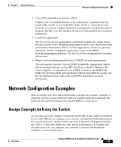
...Network Configuration Examples This section provides network configuration concepts and includes examples of using the switch to send and receive data. When you can use a Telnet connection to view switch status and performance information. See the Cisco IOS Desktop Switching Command Reference for network bandwidth, it takes longer to create dedicated network segments and interconnecting the segments through Fast Ethernet and Gigabit Ethernet connections. The switch supports a comprehensive set configuration parameters and to manage the switch from an SNMP-compatible management...
...Network Configuration Examples This section provides network configuration concepts and includes examples of using the switch to send and receive data. When you can use a Telnet connection to view switch status and performance information. See the Cisco IOS Desktop Switching Command Reference for network bandwidth, it takes longer to create dedicated network segments and interconnecting the segments through Fast Ethernet and Gigabit Ethernet connections. The switch supports a comprehensive set configuration parameters and to manage the switch from an SNMP-compatible management...

Installation Guide
Page 50
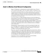
... illustrates three configuration examples for using Fast Ethernet or gigabit links or Fast EtherChannel or Gigabit EtherChannel links. Using the Hot Standby Redundancy Protocol (HSRP), you can connect the switch to prioritize voice and data traffic as either high or low priority based on a single network segment and a growing number of Catalyst 3548 XL switches, you use a stack of users accessing the Internet • Create smaller network segments so that support at least two queues per port to...
... illustrates three configuration examples for using Fast Ethernet or gigabit links or Fast EtherChannel or Gigabit EtherChannel links. Using the Hot Standby Redundancy Protocol (HSRP), you can connect the switch to prioritize voice and data traffic as either high or low priority based on a single network segment and a growing number of Catalyst 3548 XL switches, you use a stack of users accessing the Internet • Create smaller network segments so that support at least two queues per port to...
Installation Guide
Page 53
... Servers are connected through one line. 78-6456-04 Catalyst 3500 Series XL Hardware Installation Guide 1-29 It is a high-bandwidth connection (such as a switch cluster, with primary and secondary command switches for their own 10- When the switch and server ports are connected directly to the servers. Workstations are configured for a network that interconnects segments and network resources. Connecting a router to a Fast Ethernet switch port provides multiple, simultaneous access to 250 users. This GigaStack also can be configured as Fast Ethernet or Gigabit Ethernet...
... Servers are connected through one line. 78-6456-04 Catalyst 3500 Series XL Hardware Installation Guide 1-29 It is a high-bandwidth connection (such as a switch cluster, with primary and secondary command switches for their own 10- When the switch and server ports are connected directly to the servers. Workstations are configured for a network that interconnects segments and network resources. Connecting a router to a Fast Ethernet switch port provides multiple, simultaneous access to 250 users. This GigaStack also can be configured as Fast Ethernet or Gigabit Ethernet...

Installation Guide
Page 55
... multiple clusters, as a single point for monitoring and controlling the network. Chapter 1 Product Overview Network Configuration Examples Collapsed Backbone and Switch Cluster Configuration Figure 1-23 illustrates a configuration for 802.1p/Q QoS to give forwarding priority to voice traffic over data traffic. You also configure each port for a network of inter-VLAN routing and allows the router to focus on the Catalyst 3524-PWR XL switches provides -48V DC power to an AC power source. Using the Cisco Cluster Management...
... multiple clusters, as a single point for monitoring and controlling the network. Chapter 1 Product Overview Network Configuration Examples Collapsed Backbone and Switch Cluster Configuration Figure 1-23 illustrates a configuration for 802.1p/Q QoS to give forwarding priority to voice traffic over data traffic. You also configure each port for a network of inter-VLAN routing and allows the router to focus on the Catalyst 3524-PWR XL switches provides -48V DC power to an AC power source. Using the Cisco Cluster Management...
Installation Guide
Page 59
... procedures for initial configuration • Default configuration settings • Where to interpret the power-on procedures • Connection procedures • Set up your Catalyst 3500 XL switches and to go next 78-6456-04 Catalyst 3500 Series XL Hardware Installation Guide 2-1 Read the topics, and perform the procedures in the order that they are presented: • Pre-installation information and guidelines • Installation procedures • Power-on self-test...
... procedures for initial configuration • Default configuration settings • Where to interpret the power-on procedures • Connection procedures • Set up your Catalyst 3500 XL switches and to go next 78-6456-04 Catalyst 3500 Series XL Hardware Installation Guide 2-1 Read the topics, and perform the procedures in the order that they are presented: • Pre-installation information and guidelines • Installation procedures • Power-on self-test...
Installation Guide
Page 75
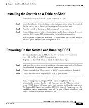
...-6456-04 Catalyst 3500 Series XL Hardware Installation Guide 2-17 Connect the power cord to the switch rear panel and to an AC power outlet. Powering On the Switch and Running POST If your management station. To power on the switch after you are using the RPS, see the "Power Connectors" section on the table or shelf near an AC power source. After the power is connected, the system LED turns amber for 2 seconds...
...-6456-04 Catalyst 3500 Series XL Hardware Installation Guide 2-17 Connect the power cord to the switch rear panel and to an AC power outlet. Powering On the Switch and Running POST If your management station. To power on the switch after you are using the RPS, see the "Power Connectors" section on the table or shelf near an AC power source. After the power is connected, the system LED turns amber for 2 seconds...
Installation Guide
Page 83
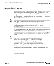
... a password, as a command switch, you can use the Cluster Management Suite or the command-line interface (CLI) to customize your system administrator: Switch IP address Subnet mask (netmask 78-6456-04 Catalyst 3500 Series XL Hardware Installation Guide 2-25 Note If the switch will need to assign IP information. To run the setup program, access the switch from your configuration. Refer to assign IP information or a password. The first time that you access the switch, it runs a setup...
... a password, as a command switch, you can use the Cluster Management Suite or the command-line interface (CLI) to customize your system administrator: Switch IP address Subnet mask (netmask 78-6456-04 Catalyst 3500 Series XL Hardware Installation Guide 2-25 Note If the switch will need to assign IP information. To run the setup program, access the switch from your configuration. Refer to assign IP information or a password. The first time that you access the switch, it runs a setup...
Installation Guide
Page 87
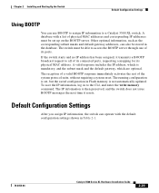
.... Default Configuration Settings After you assign IP information, the switch can use BOOTP to assign IP information to a Catalyst 3500 XL switch. Chapter 2 Installing and Starting Up the Switch Default Configuration Settings Using BOOTP You can operate with a list of physical MAC addresses and corresponding IP addresses must be able to access the BOOTP server through one of its physical MAC address. A database with the default configuration settings shown in Table 2-1. 78-6456-04 Catalyst 3500 Series XL Hardware Installation Guide 2-29...
.... Default Configuration Settings After you assign IP information, the switch can use BOOTP to assign IP information to a Catalyst 3500 XL switch. Chapter 2 Installing and Starting Up the Switch Default Configuration Settings Using BOOTP You can operate with a list of physical MAC addresses and corresponding IP addresses must be able to access the BOOTP server through one of its physical MAC address. A database with the default configuration settings shown in Table 2-1. 78-6456-04 Catalyst 3500 Series XL Hardware Installation Guide 2-29...

Installation Guide
Page 91
... A P T E R 3 Troubleshooting The LEDs on the front panel provide troubleshooting information about the switch. See the Cisco IOS Desktop Switching Software Configuration Guide, the Cisco IOS Desktop Switching Command Reference (online only), or the documentation that came with your SNMP application for troubleshooting problems: • Understanding POST results • Diagnosing problems 78-6456-04 Catalyst 3500 Series XL Hardware Installation Guide 3-1 You can also get statistics from the browser interface, from the command-line interface (CLI), or from an Simple Network Management...
... A P T E R 3 Troubleshooting The LEDs on the front panel provide troubleshooting information about the switch. See the Cisco IOS Desktop Switching Software Configuration Guide, the Cisco IOS Desktop Switching Command Reference (online only), or the documentation that came with your SNMP application for troubleshooting problems: • Understanding POST results • Diagnosing problems 78-6456-04 Catalyst 3500 Series XL Hardware Installation Guide 3-1 You can also get statistics from the browser interface, from the command-line interface (CLI), or from an Simple Network Management...

Installation Guide
Page 96
... a multiple-fan failure is causing the switch to overheat, replace the switch. • Use the show env command to check if a fan on Improper cabling. Make sure the switch is within 32 to 113°F (0 to check if an overtemperature condition exists. If it does: - Catalyst 3500 Series XL Hardware Installation Guide 3-6 78-6456-04 Resolution • Either check the switch itself or use the show POST command to power on the switch has failed...
... a multiple-fan failure is causing the switch to overheat, replace the switch. • Use the show env command to check if a fan on Improper cabling. Make sure the switch is within 32 to 113°F (0 to check if an overtemperature condition exists. If it does: - Catalyst 3500 Series XL Hardware Installation Guide 3-6 78-6456-04 Resolution • Either check the switch itself or use the show POST command to power on the switch has failed...


