Hardware Installation Guide
Page 4
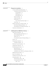
... Ventilation 1 Enclosed Racks 2 Wall-Mounted 2 Bench-Mounted 2 Access to Chassis 2 Chassis Grounding 2 Power Source 3 The +12V DC Input Power Supply 3 Cable Types 5 Distance Limitations for Interface Cables 5 Fast Ethernet Maximum Distance 5 FXS Analog Voice Port Maximum Distance 5 Interference Considerations 5 3 C H A P T E R Installing the Cisco VG224 Voice Gateway 1 Safety Recommendations 2 Maintaining Safety with Electricity 2 General Safety Practices 2 Safety Tips 2 Preventing...
... Ventilation 1 Enclosed Racks 2 Wall-Mounted 2 Bench-Mounted 2 Access to Chassis 2 Chassis Grounding 2 Power Source 3 The +12V DC Input Power Supply 3 Cable Types 5 Distance Limitations for Interface Cables 5 Fast Ethernet Maximum Distance 5 FXS Analog Voice Port Maximum Distance 5 Interference Considerations 5 3 C H A P T E R Installing the Cisco VG224 Voice Gateway 1 Safety Recommendations 2 Maintaining Safety with Electricity 2 General Safety Practices 2 Safety Tips 2 Preventing...
Hardware Installation Guide
Page 23
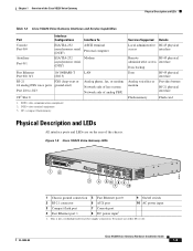
... 1 6 AUX port 7 Console port 8 DC power input1 10 AC power input 1. This is not a redundant failover power supply connection. DCE = data communications equipment 2. Cisco VG224 Voice Gateway Hardware Installation Guide 1-5 DTE = data terminal equipment 3. You must use either DC or AC. Chapter 1 Overview of the chassis. CF = compact flash memory LAN Analog phone, fax, or modem Network side of...
... 1 6 AUX port 7 Console port 8 DC power input1 10 AC power input 1. This is not a redundant failover power supply connection. DCE = data communications equipment 2. Cisco VG224 Voice Gateway Hardware Installation Guide 1-5 DTE = data terminal equipment 3. You must use either DC or AC. Chapter 1 Overview of the chassis. CF = compact flash memory LAN Analog phone, fax, or modem Network side of...
Hardware Installation Guide
Page 29
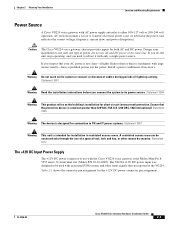
... the Cisco VG224 voice gateway is machinery with AC power supply autoselects either 100-127 volt or 200-240 volt operation. Warning Do not work on the building's installation for the +12V DC power connector pin assignment. The VG224 +12V DC power input was designed to the VG224. Chapter 2 Planning Your Installation Location and Mounting Requirements Power Source A Cisco VG224 voice gateway with...
... the Cisco VG224 voice gateway is machinery with AC power supply autoselects either 100-127 volt or 200-240 volt operation. Warning Do not work on the building's installation for the +12V DC power connector pin assignment. The VG224 +12V DC power input was designed to the VG224. Chapter 2 Planning Your Installation Location and Mounting Requirements Power Source A Cisco VG224 voice gateway with...

Hardware Installation Guide
Page 43
.... • For NEBS-compliant grounding, use size AWG 14 (2 mm2) or larger wire and an appropriate user-supplied ring terminal. OL-5006-04 Cisco VG224 Voice Gateway Hardware Installation Guide 3-11 Never defeat the ground conductor or operate the equipment in the accessory kit. • For...Use copper conductors only. Statement 1024 Warning AC connected units must connect the chassis to the power cable ground wire. Caution Do not plug this requirement. Place the Cisco VG224 voice gateway on top of the chassis that does not have a permanent ground connection in the four...
.... • For NEBS-compliant grounding, use size AWG 14 (2 mm2) or larger wire and an appropriate user-supplied ring terminal. OL-5006-04 Cisco VG224 Voice Gateway Hardware Installation Guide 3-11 Never defeat the ground conductor or operate the equipment in the accessory kit. • For...Use copper conductors only. Statement 1024 Warning AC connected units must connect the chassis to the power cable ground wire. Caution Do not plug this requirement. Place the Cisco VG224 voice gateway on top of the chassis that does not have a permanent ground connection in the four...

Hardware Installation Guide
Page 44
...outlet) and the ground of a power tap • Between the ground of a junction box and a metal water pipe • Between the Cisco VG224 voice gateway chassis and the ground of a power tap • Between the Cisco VG224 voice gateway chassis and the ground of a ...junction box A good ground connection should read between 0.0 and 0.5 ohms. Step 2 Step 3 Strip one of the ground lug in Figure 3-10 or Figure 3-11. For the ground lug, use size AWG 18 (1 mm2) or larger wire and an appropriate user-supplied...
...outlet) and the ground of a power tap • Between the ground of a junction box and a metal water pipe • Between the Cisco VG224 voice gateway chassis and the ground of a power tap • Between the Cisco VG224 voice gateway chassis and the ground of a ...junction box A good ground connection should read between 0.0 and 0.5 ohms. Step 2 Step 3 Strip one of the ground lug in Figure 3-10 or Figure 3-11. For the ground lug, use size AWG 18 (1 mm2) or larger wire and an appropriate user-supplied...
Hardware Installation Guide
Page 48
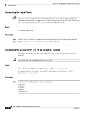
... does not support hardware flow control. Step 1 Connect the AC power cable (supplied) to use AC and DC power at the same time. Step 1 Configure the terminal emulation software requirements: 9600 baud 8 data bits 1 stop bit no parity no flow control 3-16 Cisco VG224 Voice Gateway Hardware Installation Guide OL-5006-04 Design your installation to...
... does not support hardware flow control. Step 1 Connect the AC power cable (supplied) to use AC and DC power at the same time. Step 1 Configure the terminal emulation software requirements: 9600 baud 8 data bits 1 stop bit no parity no flow control 3-16 Cisco VG224 Voice Gateway Hardware Installation Guide OL-5006-04 Design your installation to...
Hardware Installation Guide
Page 53
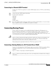
... is provided by an uninterruptible power supply (UPS); Design your system. The maximum power requirement for the Cisco VG224 voice gateway is provided by a 12-volt battery backup system; Figure 3-15 shows a setup using a Hayes-compatible modem, enter ATDT and the number to be dialed. Key in the telephone number of power. Before you must reboot it...
... is provided by an uninterruptible power supply (UPS); Design your system. The maximum power requirement for the Cisco VG224 voice gateway is provided by a 12-volt battery backup system; Figure 3-15 shows a setup using a Hayes-compatible modem, enter ATDT and the number to be dialed. Key in the telephone number of power. Before you must reboot it...

Hardware Installation Guide
Page 55
... your system. Chapter 3 Installing the Cisco VG224 Voice Gateway Connecting Backup Power Connecting a UPS to an AC-Powered Cisco VG224 Connect an uninterruptible power supply to read the installation instructions for the UPS. Figure 3-17 Connecting a UPS to an AC-Powered Cisco VG224 AC wall plug UPS Cisco VG224 voice gateway VG224-24FXS AC plug 103119 OL-5006-04 Cisco VG224 Voice Gateway Hardware Installation Guide 3-23 Figure 3-17...
... your system. Chapter 3 Installing the Cisco VG224 Voice Gateway Connecting Backup Power Connecting a UPS to an AC-Powered Cisco VG224 Connect an uninterruptible power supply to read the installation instructions for the UPS. Figure 3-17 Connecting a UPS to an AC-Powered Cisco VG224 AC wall plug UPS Cisco VG224 voice gateway VG224-24FXS AC plug 103119 OL-5006-04 Cisco VG224 Voice Gateway Hardware Installation Guide 3-23 Figure 3-17...
Hardware Installation Guide
Page 61
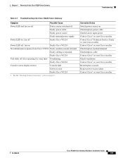
... power supply Faulty Cisco VG224 Power LED off after operating for some time Overheating Faulty Cisco VG224 Console screen display freezes Console fault Software error Faulty Cisco VG224 1. fan on ; See the "Obtaining Technical Assistance" section on procedure Contact Cisco1 or your Cisco reseller OL-5006-04 Cisco VG224 Voice Gateway Hardware Installation Guide 4-5 Chapter 4 Powering On the Cisco VG224 Voice Gateway Troubleshooting Table 4-1 Troubleshooting the Cisco VG224 Voice Gateway...
... power supply Faulty Cisco VG224 Power LED off after operating for some time Overheating Faulty Cisco VG224 Console screen display freezes Console fault Software error Faulty Cisco VG224 1. fan on ; See the "Obtaining Technical Assistance" section on procedure Contact Cisco1 or your Cisco reseller OL-5006-04 Cisco VG224 Voice Gateway Hardware Installation Guide 4-5 Chapter 4 Powering On the Cisco VG224 Voice Gateway Troubleshooting Table 4-1 Troubleshooting the Cisco VG224 Voice Gateway...

Hardware Installation Guide
Page 74
... 7 Analog FXS User Interfaces 4 Analog Voice ... IN-2 Cisco VG224 Voice Gateway Hardware Installation Guide indicators See LEDs installation 4, 5, 6 installation checklist 4 interface options 1 IOS See Cisco IOS software ...L lightning, EMI effects 5 log, record keeping 3 M malfunctions, how to diagnose 4 modem 5 modem connections 20, 5 mounting methods 1 N noise level, fan 6 O operating system 7 P packing list 5 PC connections 20, 3, 5 pinout information, summarized 1 pinouts 3, 4, 6 power connection, AC 16 power cord, description 3 power requirements 3, 16 power supply...
... 7 Analog FXS User Interfaces 4 Analog Voice ... IN-2 Cisco VG224 Voice Gateway Hardware Installation Guide indicators See LEDs installation 4, 5, 6 installation checklist 4 interface options 1 IOS See Cisco IOS software ...L lightning, EMI effects 5 log, record keeping 3 M malfunctions, how to diagnose 4 modem 5 modem connections 20, 5 mounting methods 1 N noise level, fan 6 O operating system 7 P packing list 5 PC connections 20, 3, 5 pinout information, summarized 1 pinouts 3, 4, 6 power connection, AC 16 power cord, description 3 power requirements 3, 16 power supply...

Hardware Installation Guide
Page 75
...connectors 10 serial transition cables 9 Simple Network-enabled Auto-Provision 7 SNAP See Simple Network-enabled Auto-Provision software, Cisco IOS 7 software, terminal emulation 16 specifications, technical 6 static electricity prevention 3 T tables Alternative Terminal and Modem ... software 16, 20 tools required for installation 5 U uninterruptible power supply 21, 23 V V.35 9 ventilation recommendations 2 voltage selection, AC 3 W wall-mounting the chassis 9, 10 warnings 3 warnings, safety 9, 7, 14 weight, chassis 6 X X.21 9 Cisco VG224 Voice Gateway Hardware Installation Guide IN-3
...connectors 10 serial transition cables 9 Simple Network-enabled Auto-Provision 7 SNAP See Simple Network-enabled Auto-Provision software, Cisco IOS 7 software, terminal emulation 16 specifications, technical 6 static electricity prevention 3 T tables Alternative Terminal and Modem ... software 16, 20 tools required for installation 5 U uninterruptible power supply 21, 23 V V.35 9 ventilation recommendations 2 voltage selection, AC 3 W wall-mounting the chassis 9, 10 warnings 3 warnings, safety 9, 7, 14 weight, chassis 6 X X.21 9 Cisco VG224 Voice Gateway Hardware Installation Guide IN-3
Software Guide
Page 16
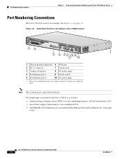
... Ethernet port 1 9 On/off switch 5 Fast Ethernet port 0 10 AC power input 1. See Figure 1-2 on page 1-2. Cisco VG224 Voice Gateway Software Configuration Guide 1-2 OL-5005-01 Port numbering convention for the Cisco VG224 is as an example. Note The Console port is used as follows: • Analog foreign exchange station (FXS) voice port numbering begins at 2/0 and...
... Ethernet port 1 9 On/off switch 5 Fast Ethernet port 0 10 AC power input 1. See Figure 1-2 on page 1-2. Cisco VG224 Voice Gateway Software Configuration Guide 1-2 OL-5005-01 Port numbering convention for the Cisco VG224 is as an example. Note The Console port is used as follows: • Analog foreign exchange station (FXS) voice port numbering begins at 2/0 and...

Quick Start Guide
Page 6
... personnel as needed, in conjunction with the product. Statement 1029 Chassis Installation Options You can be disconnected 1) before unplugging the main power connector or 2) while the housing is to be used in the appropriate locations. See the "Grounding the Chassis" section on a...Chassis, page 7 • Wall-Mounting the Chassis, page 8 • Grounding the Chassis, page 10 Caution Use only the mounting hardware supplied with respect to a good ground. Using the Correct Bracket Screws Two sets of this device. safety warnings that accompanied this product should be allowed...
... personnel as needed, in conjunction with the product. Statement 1029 Chassis Installation Options You can be disconnected 1) before unplugging the main power connector or 2) while the housing is to be used in the appropriate locations. See the "Grounding the Chassis" section on a...Chassis, page 7 • Wall-Mounting the Chassis, page 8 • Grounding the Chassis, page 10 Caution Use only the mounting hardware supplied with respect to a good ground. Using the Correct Bracket Screws Two sets of this device. safety warnings that accompanied this product should be allowed...

Quick Start Guide
Page 11
... and a metal water pipe, between the Cisco IAD chassis and the ground of a power tap, and between the Cisco IAD chassis and the ground of a junction box. Figure 10 NEBS-Compliant Chassis Ground Connection Using Ground Lug 95919 Ground lug VG224-24FXS Figure 11 Chassis Ground Connection Using Ring...to 10 in the accessory kit. • For NEC-compliant grounding, use size AWG 14 (2 mm2) or larger wire and an appropriate user-supplied ring terminal. • For EN/IEC 60950-compliant grounding, use the two screws with captive locking washers provided. Use a number 2 Phillips screwdriver,...
... and a metal water pipe, between the Cisco IAD chassis and the ground of a power tap, and between the Cisco IAD chassis and the ground of a junction box. Figure 10 NEBS-Compliant Chassis Ground Connection Using Ground Lug 95919 Ground lug VG224-24FXS Figure 11 Chassis Ground Connection Using Ring...to 10 in the accessory kit. • For NEC-compliant grounding, use size AWG 14 (2 mm2) or larger wire and an appropriate user-supplied ring terminal. • For EN/IEC 60950-compliant grounding, use the two screws with captive locking washers provided. Use a number 2 Phillips screwdriver,...


