
Administration Guide
Page 3
Table of Contents Port Status 45 PoE Status 45 Port Configuration 46 Port Settings 46 PoE Settings 47 System Mode (Layer 2 / Layer 3) Selection 48 Help 49 Logout 50 5 Web Utility Configuration 51 Connecting to the Switch with the Web-Based Utility 51 Using Menus in the Web-Based Utility 51 Viewing On-line Help 52 A Contacts... Warranty Service 57 Technical Support 57 D Federal Communication Commission Interference Statement . . 58 Industry Canada Statement 58 EC Declaration of Conformity (Europe) 58 E Specifications 59 SGE2010/SGE2010P Administration Guide ii
Table of Contents Port Status 45 PoE Status 45 Port Configuration 46 Port Settings 46 PoE Settings 47 System Mode (Layer 2 / Layer 3) Selection 48 Help 49 Logout 50 5 Web Utility Configuration 51 Connecting to the Switch with the Web-Based Utility 51 Using Menus in the Web-Based Utility 51 Viewing On-line Help 52 A Contacts... Warranty Service 57 Technical Support 57 D Federal Communication Commission Interference Statement . . 58 Industry Canada Statement 58 EC Declaration of Conformity (Europe) 58 E Specifications 59 SGE2010/SGE2010P Administration Guide ii

Administration Guide
Page 5
... are 48-port, layer-2 Ethernet switches that affordably expand the capability of the Linksys system. A blinking red FAN LED indicates that this Switch is operating properly. The green Act/Link LEDs light up to indicate a functional network link through the corresponding port with an attached device. SGE2010/SGE2010P Administration ... LED lights up to indicate that the Switch is powered on that RPS is pressed for more than 10 seconds, the Switch will be used to supply power to Know the SGE2010/SGE2010P This chapter describes the ports, LEDs, and other features on the front...
... are 48-port, layer-2 Ethernet switches that affordably expand the capability of the Linksys system. A blinking red FAN LED indicates that this Switch is operating properly. The green Act/Link LEDs light up to indicate a functional network link through the corresponding port with an attached device. SGE2010/SGE2010P Administration ... LED lights up to indicate that the Switch is powered on that RPS is pressed for more than 10 seconds, the Switch will be used to supply power to Know the SGE2010/SGE2010P This chapter describes the ports, LEDs, and other features on the front...

Administration Guide
Page 6
... miniGBIC1, miniGBIC2, miniGBIC3, and miniGBIC4, respectively. The mini-GBIC (gigabit interface converter) port is a connection point for more information about stacking, refer to Know the SGE2010/SGE2010P Feature 1-48 miniGBIC1-4 Description The Switch is 360W available to 1000Mbps. Each mini-GBIC port provides a link to a high-speed network segment or individual workstation at speeds of...
... miniGBIC1, miniGBIC2, miniGBIC3, and miniGBIC4, respectively. The mini-GBIC (gigabit interface converter) port is a connection point for more information about stacking, refer to Know the SGE2010/SGE2010P Feature 1-48 miniGBIC1-4 Description The Switch is 360W available to 1000Mbps. Each mini-GBIC port provides a link to a high-speed network segment or individual workstation at speeds of...

Administration Guide
Page 12
...save the settings to use the HyperTerminal to connect to your switch for basic configuration of the switch and management of the switch. The switch features a menu-driven console interface for the first time, you connect to Your Switch with Telnet," on page 12 • Logging On to ...System Configuration (see page 13) • Port Status (see page 44) • Port Configuration (see page 46) • System Mode (Layer 2 / Layer 3) Selection (see page 48) • Help (see page 49) • Logout (see page 50) Connecting to your switch. Telnet to perform basic configuration of your ...
...save the settings to use the HyperTerminal to connect to your switch for basic configuration of the switch and management of the switch. The switch features a menu-driven console interface for the first time, you connect to Your Switch with Telnet," on page 12 • Logging On to ...System Configuration (see page 13) • Port Status (see page 44) • Port Configuration (see page 46) • System Mode (Layer 2 / Layer 3) Selection (see page 48) • Help (see page 49) • Logout (see page 50) Connecting to your switch. Telnet to perform basic configuration of your ...

Administration Guide
Page 16
... provides access to screens where you need to restore default settings, reset the switch to the factory default configuration, or reboot the system. 1. System Mode (Layer 2 / Layer 3) Selection (see page 16) SGE2010/SGE2010P Administration Guide 13 Management Settings (see page 48) 5. Port Status (see page 14) 2. System Information (see page 44) 3. You also will use...
... provides access to screens where you need to restore default settings, reset the switch to the factory default configuration, or reboot the system. 1. System Mode (Layer 2 / Layer 3) Selection (see page 16) SGE2010/SGE2010P Administration Guide 13 Management Settings (see page 48) 5. Port Status (see page 14) 2. System Information (see page 44) 3. You also will use...
Administration Guide
Page 51
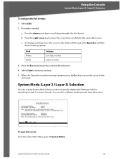
... from this screen: From the Switch Main Menu, press 4. You can use the System Mode Selection screen to the Action list. 4. Proceed as needed: a. Select Save to scroll down arrow key to save your settings 5. SGE2010/SGE2010P Administration Guide 48 Press the right arrow key to... move the cursor to specify whether the Ethernet switch is operating in Layer 2 or Layer 3 mode. c. Press the down through the list of ports. To open this screen. To change a ...
... from this screen: From the Switch Main Menu, press 4. You can use the System Mode Selection screen to the Action list. 4. Proceed as needed: a. Select Save to scroll down arrow key to save your settings 5. SGE2010/SGE2010P Administration Guide 48 Press the right arrow key to... move the cursor to specify whether the Ethernet switch is operating in Layer 2 or Layer 3 mode. c. Press the down through the list of ports. To open this screen. To change a ...

Administration Guide
Page 62
... VLANs Protocol-based VLAN Management VLAN Multicast TV VLAN Private VLAN Edge (PVE) GVRP Head of layer 3 traffic SGE2010/SGE2010P Administration Guide 59 E Specifications Model Ports Cabling Type Switching Capacity Forwarding Capacity LEDs Stack Operation Buttons Layer 2 options Layer 3 options • SGE2010 48-port 10/100/1000 Ethernet Switch • SGE2010P 48-port 10/100/1000 Ethernet Switch with PoE •...
... VLANs Protocol-based VLAN Management VLAN Multicast TV VLAN Private VLAN Edge (PVE) GVRP Head of layer 3 traffic SGE2010/SGE2010P Administration Guide 59 E Specifications Model Ports Cabling Type Switching Capacity Forwarding Capacity LEDs Stack Operation Buttons Layer 2 options Layer 3 options • SGE2010 48-port 10/100/1000 Ethernet Switch • SGE2010P 48-port 10/100/1000 Ethernet Switch with PoE •...


