

Administration Guide
Page 4
... Factory Default Mode 23 Understanding LED Indicators 23 Stack Troubleshooting and Maintenance 24 Replacing a Failed Member Stack Unit in an Operational Stack 24 Replacing a Failed Stack Master Unit in an Operational Stack 26 Splitting a Stack 27 Merging Two Stacks 29 Understanding Stacking Cable Failure 31 Inserting Too Many Units into a Stack 31 Inserting a Standalone Unit into a Running Stack 32 Chapter 4: Console Configuration 33 Overview 33 Configuring the HyperTerminal Application 33 Connecting to the Switch using Telnet or SSH...
... Factory Default Mode 23 Understanding LED Indicators 23 Stack Troubleshooting and Maintenance 24 Replacing a Failed Member Stack Unit in an Operational Stack 24 Replacing a Failed Stack Master Unit in an Operational Stack 26 Splitting a Stack 27 Merging Two Stacks 29 Understanding Stacking Cable Failure 31 Inserting Too Many Units into a Stack 31 Inserting a Standalone Unit into a Running Stack 32 Chapter 4: Console Configuration 33 Overview 33 Configuring the HyperTerminal Application 33 Connecting to the Switch using Telnet or SSH...
Administration Guide
Page 6
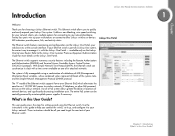
.... It delivers non-blocking, wire speed switching for your web browser, or the console interface. The "P" model of the Ethernet switch supports Power over Ethernet (PoE) which eliminates the need to get the most out of network devices, and significantly decreasing installation costs. With Simple Network Time Protocol (SNTP), the Ethernet switch can be all facets of the system state, and the Simple Network Management Protocol (SNMP) protocol. Use the instructions in this User Guide?
.... It delivers non-blocking, wire speed switching for your web browser, or the console interface. The "P" model of the Ethernet switch supports Power over Ethernet (PoE) which eliminates the need to get the most out of network devices, and significantly decreasing installation costs. With Simple Network Time Protocol (SNTP), the Ethernet switch can be all facets of the system state, and the Simple Network Management Protocol (SNMP) protocol. Use the instructions in this User Guide?

Administration Guide
Page 8
... -Ethernet (PoE) which support network speeds of 10Mbps, 100Mbps, and 1000Mbps. Chapter Getting to Know the Switch Overview These two versions are 24-port, layer-2 Ethernet switches that expand the capability of numerous functions. For more details, refer to "Reset Switch," on page 6. RESET Switch. Stack ID. Gigabit Interface Converter (mini-GBIC) Uplink Ports. If stacking is active, indicates the ID 4 number of the Ethernet switch power, fan, RPS connectivity, and stack master. The Front Panel The Switch's LEDs and Ethernet ports are listed...
... -Ethernet (PoE) which support network speeds of 10Mbps, 100Mbps, and 1000Mbps. Chapter Getting to Know the Switch Overview These two versions are 24-port, layer-2 Ethernet switches that expand the capability of numerous functions. For more details, refer to "Reset Switch," on page 6. RESET Switch. Stack ID. Gigabit Interface Converter (mini-GBIC) Uplink Ports. If stacking is active, indicates the ID 4 number of the Ethernet switch power, fan, RPS connectivity, and stack master. The Front Panel The Switch's LEDs and Ethernet ports are listed...

Administration Guide
Page 9
...) LEDs flash to indicate that the Ethernet switch is powered by a remote power supply (RPS), this Switch is 1 to 8. Range is stacked and the corresponding number indicates its stack ID. Uplink Port LEDs Act/Link Gigabit The green Act/Link LEDs light to indicate a functional network link through the corresponding port with an attached device. If the Ethernet switch is operating properly. FAN A green FAN LED lights to indicate that the cooling fan is powered by internal power supplies. A blinking red FAN LED indicates that the cooling fan has failed...
...) LEDs flash to indicate that the Ethernet switch is powered by a remote power supply (RPS), this Switch is 1 to 8. Range is stacked and the corresponding number indicates its stack ID. Uplink Port LEDs Act/Link Gigabit The green Act/Link LEDs light to indicate a functional network link through the corresponding port with an attached device. If the Ethernet switch is operating properly. FAN A green FAN LED lights to indicate that the cooling fan is powered by internal power supplies. A blinking red FAN LED indicates that the cooling fan has failed...
Administration Guide
Page 10
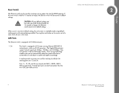
... paper clip into the RESET opening. In stacking mode, two ports are lost when you hold the Reset button for stacking. CAUTION: All user-defined settings are used for 10 seconds or longer; The Gigabit Ethernet ports support network speeds of a stack resets all units in the stack. By default, the stacking ports are shared with GBIC1, GBIC3, GBIC2, GBIC4 respectively. Chapter Reset Switch The Ethernet switch can operate in half and full-duplex modes. the Ethernet switch reverts to Know...
... paper clip into the RESET opening. In stacking mode, two ports are lost when you hold the Reset button for stacking. CAUTION: All user-defined settings are used for 10 seconds or longer; The Gigabit Ethernet ports support network speeds of a stack resets all units in the stack. By default, the stacking ports are shared with GBIC1, GBIC3, GBIC2, GBIC4 respectively. Chapter Reset Switch The Ethernet switch can operate in half and full-duplex modes. the Ethernet switch reverts to Know...

Administration Guide
Page 11
... 5e Ethernet cable with the Switch. For more details, refer to 1000Mbps. The Power port is where you can be damaged if the incorrect power cord is used. DC INPUT FOR REMOTE POWER SUPPLY SPECIFIED IN MANUAL +12V, 7.5A 3 RPS Port. The unit may be uplinked via fiber or copper to a PC's serial port for a mini-GBIC expansion module, so the Switch can 2 connect a serial cable to another switch. Console Port. For more details, refer to...
... 5e Ethernet cable with the Switch. For more details, refer to 1000Mbps. The Power port is where you can be damaged if the incorrect power cord is used. DC INPUT FOR REMOTE POWER SUPPLY SPECIFIED IN MANUAL +12V, 7.5A 3 RPS Port. The unit may be uplinked via fiber or copper to a PC's serial port for a mini-GBIC expansion module, so the Switch can 2 connect a serial cable to another switch. Console Port. For more details, refer to...
Administration Guide
Page 17
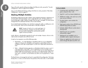
... stack mode is reset. A standalone switch does not participate in a stack even if physically connected to a stack. • Settings are available to user in a stack mode (ports 12 and 24 on GE units, and ports G1 and G2 on page 33 for regular network connections. • By factory default, Ethernet switches boot in the stack must run the same version of software. • The Stack Master switch maintains the configuration. The Stack Master unit manages the stack and is downloaded...
... stack mode is reset. A standalone switch does not participate in a stack even if physically connected to a stack. • Settings are available to user in a stack mode (ports 12 and 24 on GE units, and ports G1 and G2 on page 33 for regular network connections. • By factory default, Ethernet switches boot in the stack must run the same version of software. • The Stack Master switch maintains the configuration. The Stack Master unit manages the stack and is downloaded...

Administration Guide
Page 18
... as stacking ports and cannot be used as the Master-Backup. Connecting Cabling for Stacking When the Ethernet switch is in a stack is assigned as the Master Unit, the next powered unit is assigned as network ports. The first powered Ethernet switch in stacking mode, ports 12 and 24 are assigned Stack IDs in the Stack ID. Ports GBIC3 and GBIC4 can also be used as regular ports. Chapter runs a slave version of the switching algorithm...
... as stacking ports and cannot be used as the Master-Backup. Connecting Cabling for Stacking When the Ethernet switch is in a stack is assigned as the Master Unit, the next powered unit is assigned as network ports. The first powered Ethernet switch in stacking mode, ports 12 and 24 are assigned Stack IDs in the Stack ID. Ports GBIC3 and GBIC4 can also be used as regular ports. Chapter runs a slave version of the switching algorithm...

Administration Guide
Page 19
... the stacking ports, using standard Ethernet cables. 3. Chapter 3: Connecting the Switch 14 Managing Stacks Power the units on . Building Manually-Configured Stacks You can manually configure stacks, including choosing a specific unit as the Stack Master. Connect the units physically to a Running Stack 1. Power the units on . If a serial console connection is indicated by restoring them to the factory default mode. You must assign a unique Unit ID (from 1 to 8) to the factory default mode. 2. Reset all relevant units to by holding the reset button for...
... the stacking ports, using standard Ethernet cables. 3. Chapter 3: Connecting the Switch 14 Managing Stacks Power the units on . Building Manually-Configured Stacks You can manually configure stacks, including choosing a specific unit as the Stack Master. Connect the units physically to a Running Stack 1. Power the units on . If a serial console connection is indicated by restoring them to the factory default mode. You must assign a unique Unit ID (from 1 to 8) to the factory default mode. 2. Reset all relevant units to by holding the reset button for...

Administration Guide
Page 20
... Stack Resiliency Stacks can impact system performance. 5. Reset the units to be configured in your network can be added by using the Stack Management Interface through the console port, by Telnet, or by restoring them to the high resiliency in a stack has an assigned unique Unit ID number. Connect the units physically to make this assignment permanent. We recommend configuring the stack in ring topology, due to the factory default mode...
... Stack Resiliency Stacks can impact system performance. 5. Reset the units to be configured in your network can be added by using the Stack Management Interface through the console port, by Telnet, or by restoring them to the high resiliency in a stack has an assigned unique Unit ID number. Connect the units physically to make this assignment permanent. We recommend configuring the stack in ring topology, due to the factory default mode...

Administration Guide
Page 31
... become the new Stack Master. However, because the running stack Backup Master has a longer runtime (if it has been running for more than 10 minutes) it . Chapter Linksys One Ready Communications Solution 3 Replacing a Failed Stack Master Unit in factory default mode), it is not joined to run as long as all traffic has been routed around the failed unit using the Master Discovery...
... become the new Stack Master. However, because the running stack Backup Master has a longer runtime (if it has been running for more than 10 minutes) it . Chapter Linksys One Ready Communications Solution 3 Replacing a Failed Stack Master Unit in factory default mode), it is not joined to run as long as all traffic has been routed around the failed unit using the Master Discovery...

Administration Guide
Page 33
... period of time until synchronization (unit and port configuration) is split in each of Stack Master failure and takes over and manages the remaining units as a stack while keeping its previous Unit ID number. The Stack Master notifies the system administrator (using SYSLOG messages and SNMP traps). • The partial stacks both groups will function. Chapter 3: Connecting the Switch 28 Stack Troubleshooting and Maintenance Because...
... period of time until synchronization (unit and port configuration) is split in each of Stack Master failure and takes over and manages the remaining units as a stack while keeping its previous Unit ID number. The Stack Master notifies the system administrator (using SYSLOG messages and SNMP traps). • The partial stacks both groups will function. Chapter 3: Connecting the Switch 28 Stack Troubleshooting and Maintenance Because...
Administration Guide
Page 38
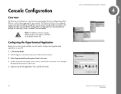
... a telnet connection. Click the Start button. 2. Select Communications. 3. Linksys One Ready Communications Solution 4 33 Chapter 4: Console Configuration Overview Chapter Console Configuration Overview The Ethernet switch features a menu-based console interface for basic configuration of the Ethernet switch and management of connection is setup by default to configure the HyperTerminal application on the default VLAN 100. Configuring the HyperTerminal Application Before you use the console interface, you will need to obtain its IP address via DHCP on your network...
... a telnet connection. Click the Start button. 2. Select Communications. 3. Linksys One Ready Communications Solution 4 33 Chapter 4: Console Configuration Overview Chapter Console Configuration Overview The Ethernet switch features a menu-based console interface for basic configuration of the Ethernet switch and management of connection is setup by default to configure the HyperTerminal application on the default VLAN 100. Configuring the HyperTerminal Application Before you use the console interface, you will need to obtain its IP address via DHCP on your network...

Administration Guide
Page 40
... through the Console or Telnet Interface The management screens consist of a series of your Ethernet switch (obtained from your Ethernet switch. The bottom of the console interface, use the Esc key to go to the Switch using the IP address of your DHCP server or the console interface), you highlight it; Linksys One Ready Communications Solution 4 35 Chapter 4: Console Configuration Connecting to the action menu. Open a telnet session using Telnet or SSH Type the user name and password. 4. Press the...
... through the Console or Telnet Interface The management screens consist of a series of your Ethernet switch (obtained from your Ethernet switch. The bottom of the console interface, use the Esc key to go to the Switch using the IP address of your DHCP server or the console interface), you highlight it; Linksys One Ready Communications Solution 4 35 Chapter 4: Console Configuration Connecting to the action menu. Open a telnet session using Telnet or SSH Type the user name and password. 4. Press the...

Administration Guide
Page 41
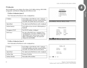
Port Configuration 4. File Management 7. Reboot System 9. Chapter 4: Console Configuration 36 Configuring the Switch through the Console or Telnet Interface System Mode (Layer 2 / Layer 3) Selection 5. Help System Configuration Menu On the System Configuration Menu screen, you have these choices: 1. Security Settings 5. System Configuration Menu 2. Back to main menu System Information Use this screen to check firmware versions and general system information for the Ethernet switch. User & Password Settings 4. Restore System Default Settings 8. IP ...
Port Configuration 4. File Management 7. Reboot System 9. Chapter 4: Console Configuration 36 Configuring the Switch through the Console or Telnet Interface System Mode (Layer 2 / Layer 3) Selection 5. Help System Configuration Menu On the System Configuration Menu screen, you have these choices: 1. Security Settings 5. System Configuration Menu 2. Back to main menu System Information Use this screen to check firmware versions and general system information for the Ethernet switch. User & Password Settings 4. Restore System Default Settings 8. IP ...
Administration Guide
Page 48
... displayed. Linksys One Ready Communications Solution 4 43 Chapter 4: Console Configuration Configuring the Switch through the Console or Telnet Interface The status of the Ethernet switch is displayed. The number of interface. Verify that the address you want the Ethernet switch to the Ethernet switch, then enter the IP settings and select DISABLE. IP Address Subnet Mask Default Gateway Management VLAN DHCP client The IP Address of the DHCP client is correct and does not conflict with another...
... displayed. Linksys One Ready Communications Solution 4 43 Chapter 4: Console Configuration Configuring the Switch through the Console or Telnet Interface The status of the Ethernet switch is displayed. The number of interface. Verify that the address you want the Ethernet switch to the Ethernet switch, then enter the IP settings and select DISABLE. IP Address Subnet Mask Default Gateway Management VLAN DHCP client The IP Address of the DHCP client is correct and does not conflict with another...
Administration Guide
Page 51
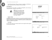
... after reboot. NOTE: There are complete, press the Esc key to return to the Action menu, and select Save to upload or download files, such as the startup configuration, boot, or image file, using a TFTP server. Chapter 4: Console Configuration 46 Configuring the Switch through the Console or Telnet Interface Specify the source and destination of the file, the file name, and the IP address of the file server where the upgrade file is replaced. File Management The File Management screen...
... after reboot. NOTE: There are complete, press the Esc key to return to the Action menu, and select Save to upload or download files, such as the startup configuration, boot, or image file, using a TFTP server. Chapter 4: Console Configuration 46 Configuring the Switch through the Console or Telnet Interface Specify the source and destination of the file, the file name, and the IP address of the file server where the upgrade file is replaced. File Management The File Management screen...

Administration Guide
Page 52
... if you want to continue. To reset stacking configuration, use the hardware reset button on the Ethernet switch. 47 Chapter 4: Console Configuration Configuring the Switch through all values except stacking configuration (stacking mode, stacking ports, and auto-numbering settings are automatically assigned to the factory default settings, select Restore System Default Settings and press the Enter key. You will appear. After the Ethernet switch has rebooted, the Switch Main Menu screen will be asked if you want to continue. To view the status of the Ethernet switch.
... if you want to continue. To reset stacking configuration, use the hardware reset button on the Ethernet switch. 47 Chapter 4: Console Configuration Configuring the Switch through all values except stacking configuration (stacking mode, stacking ports, and auto-numbering settings are automatically assigned to the factory default settings, select Restore System Default Settings and press the Enter key. You will appear. After the Ethernet switch has rebooted, the Switch Main Menu screen will be asked if you want to continue. To view the status of the Ethernet switch.
Administration Guide
Page 55
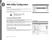
... setup by default to the address field of the Ethernet switch is with the Linksys One Portal - To access on-line help functionality for a particular screen, click on the Help button located on the default VLAN 100. Accessing the Web-based Utility To access the web-based utility, enter the IP address of the Ethernet switch to obtain its address using the Console configuration or the Linksys One Administrator screen. For example: type...
... setup by default to the address field of the Ethernet switch is with the Linksys One Portal - To access on-line help functionality for a particular screen, click on the Help button located on the default VLAN 100. Accessing the Web-based Utility To access the web-based utility, enter the IP address of the Ethernet switch to obtain its address using the Console configuration or the Linksys One Administrator screen. For example: type...
Administration Guide
Page 65
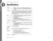
.../100/1000 ports (SGE2000P only) • Power budget allows for max power of 15.4W on up to 12 ports simultaneously 12.8 Gbps non-blocking Power, Fan, Link/Act, PoE, Speed, RPS, Master, Stack ID 1 - 8 • Up to 8 units in a stack (192 ports) • Hot Insertion and removal • Linksys 24-port Gigabit Ethernet switch • Master and Backup master for resilient stack control • Auto-numbering or manual configuration of units in stack Reset Button Appendix E: Specifications 60
.../100/1000 ports (SGE2000P only) • Power budget allows for max power of 15.4W on up to 12 ports simultaneously 12.8 Gbps non-blocking Power, Fan, Link/Act, PoE, Speed, RPS, Master, Stack ID 1 - 8 • Up to 8 units in a stack (192 ports) • Hot Insertion and removal • Linksys 24-port Gigabit Ethernet switch • Master and Backup master for resilient stack control • Auto-numbering or manual configuration of units in stack Reset Button Appendix E: Specifications 60


