

Administration Guide
Page 4
... Factory Default Mode 23 Understanding LED Indicators 23 Stack Troubleshooting and Maintenance 24 Replacing a Failed Member Stack Unit in an Operational Stack 24 Replacing a Failed Stack Master Unit in an Operational Stack 25 Splitting a Stack 27 Merging Two Stacks 29 Understanding Stacking Cable Failure 31 Inserting Too Many Units into a Stack 31 Inserting a Standalone Unit into a Running Stack 32 Chapter 4: Console Configuration 33 Overview 33 Configuring the HyperTerminal Application 33 Connecting to the Switch using Telnet or SSH...
... Factory Default Mode 23 Understanding LED Indicators 23 Stack Troubleshooting and Maintenance 24 Replacing a Failed Member Stack Unit in an Operational Stack 24 Replacing a Failed Stack Master Unit in an Operational Stack 25 Splitting a Stack 27 Merging Two Stacks 29 Understanding Stacking Cable Failure 31 Inserting Too Many Units into a Stack 31 Inserting a Standalone Unit into a Running Stack 32 Chapter 4: Console Configuration 33 Overview 33 Configuring the HyperTerminal Application 33 Connecting to the Switch using Telnet or SSH...
Administration Guide
Page 7
... of the Ethernet switch supports Power over Ethernet (PoE) which eliminates the need to wireless network, IP telephony, or other Linksys switches or devices. This Ethernet switch allows you to your Linksys One system. The "P" model of network devices, and significantly decreasing installation costs. LED indicators provide power, link, and activity status. It delivers non-blocking, wire speed switching for your web browser, or the console interface. Chapter 1: Introduction 1 What's in this User Guide?
... of the Ethernet switch supports Power over Ethernet (PoE) which eliminates the need to wireless network, IP telephony, or other Linksys switches or devices. This Ethernet switch allows you to your Linksys One system. The "P" model of network devices, and significantly decreasing installation costs. LED indicators provide power, link, and activity status. It delivers non-blocking, wire speed switching for your web browser, or the console interface. Chapter 1: Introduction 1 What's in this User Guide?
Administration Guide
Page 9
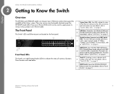
.... RESET Switch. These two versions are functionally identical except the SFE2000P model offers Power-over Ethernet cable. These ports can also be used to supply power to "Uplink Ports," on page 4. For more details, refer to various Linksys products over -Ethernet (PoE) which support network speeds of the Linksys system. Resets the SFE2000/SFE2000P 6 Ethernet switch. For more details, refer to "LAN Ports," on page 6. For more details, refer to "Uplink Ports," on page 5. Stack ID. Uplink Ports. Four LEDs indicate the status...
.... RESET Switch. These two versions are functionally identical except the SFE2000P model offers Power-over Ethernet cable. These ports can also be used to supply power to "Uplink Ports," on page 4. For more details, refer to various Linksys products over -Ethernet (PoE) which support network speeds of the Linksys system. Resets the SFE2000/SFE2000P 6 Ethernet switch. For more details, refer to "LAN Ports," on page 6. For more details, refer to "Uplink Ports," on page 5. Stack ID. Uplink Ports. Four LEDs indicate the status...

Administration Guide
Page 10
.... The Gigabit LED lights indicate a Gigabit connection on that port. A green FAN LED lights to indicate a functional network link through the corresponding port with an attached device. A green MST LED indicates that this LED blinks red. System Status LEDs PWR FAN RPS MST A green PWR LED lights to indicate that the Ethernet switch is powered by a remote power supply (RPS), this Ethernet switch is a stack master. The Act (Activity) LEDs flash to Know the Switch The Front Panel Chapter Uplink Port LEDs Act/Link Gigabit The green Act/Link LEDs light to indicate...
.... The Gigabit LED lights indicate a Gigabit connection on that port. A green FAN LED lights to indicate a functional network link through the corresponding port with an attached device. A green MST LED indicates that this LED blinks red. System Status LEDs PWR FAN RPS MST A green PWR LED lights to indicate that the Ethernet switch is powered by a remote power supply (RPS), this Ethernet switch is a stack master. The Act (Activity) LEDs flash to Know the Switch The Front Panel Chapter Uplink Port LEDs Act/Link Gigabit The green Act/Link LEDs light to indicate...
Administration Guide
Page 11
The Fast Ethernet ports support network speeds of a stack resets all units in half and full-duplex modes. Auto-sensing technology enables each port to automatically detect the speed of the device connected to Know the Switch 5 The Front Panel Chapter 2: Getting to it, and adjust its speed and duplex accordingly. CAUTION: All user-defined settings are lost when you hold the Reset button for 10 seconds or longer, the Ethernet switch will be reset by inserting...
The Fast Ethernet ports support network speeds of a stack resets all units in half and full-duplex modes. Auto-sensing technology enables each port to automatically detect the speed of the device connected to Know the Switch 5 The Front Panel Chapter 2: Getting to it, and adjust its speed and duplex accordingly. CAUTION: All user-defined settings are lost when you hold the Reset button for 10 seconds or longer, the Ethernet switch will be reset by inserting...
Administration Guide
Page 12
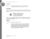
... Ethernet (IEEE 802.3ab) uplink ports which support network speeds of 10Mbps, 100Mbps, and 1000Mbps. The mini-GBIC port is a connection point for configuration. The Console port is where you will 1 connect the power cord. Use only ports G1/ G2 for stacking. Each mini-GBIC port provides a link to Know the Switch The Back Panel Chapter Linksys One Ready Communications Solution Uplink Ports 2 The Switch is equipped with the Switch. For more details, refer...
... Ethernet (IEEE 802.3ab) uplink ports which support network speeds of 10Mbps, 100Mbps, and 1000Mbps. The mini-GBIC port is a connection point for configuration. The Console port is where you will 1 connect the power cord. Use only ports G1/ G2 for stacking. Each mini-GBIC port provides a link to Know the Switch The Back Panel Chapter Linksys One Ready Communications Solution Uplink Ports 2 The Switch is equipped with the Switch. For more details, refer...
Administration Guide
Page 18
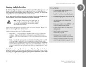
... a single Ethernet switch. Chapter Linksys One Ready Communications Solution Stacking Multiple Switches Stacking Highlights 3 The Stacking configuration provides multiple switch management through which allows the applications running the same software version. • By factory default, Ethernet switches boot in a stack mode (ports 12 and 24 on GE units, and ports G1 and G2 on the master unit to control the resources of the member unit. 12 Chapter 3: Connecting the Switch Stacking Multiple Switches The Stack Master unit manages the stack and...
... a single Ethernet switch. Chapter Linksys One Ready Communications Solution Stacking Multiple Switches Stacking Highlights 3 The Stacking configuration provides multiple switch management through which allows the applications running the same software version. • By factory default, Ethernet switches boot in a stack mode (ports 12 and 24 on GE units, and ports G1 and G2 on the master unit to control the resources of the member unit. 12 Chapter 3: Connecting the Switch Stacking Multiple Switches The Stack Master unit manages the stack and...

Administration Guide
Page 20
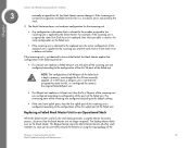
... through the stacking ports, using standard Ethernet cables. 9. Assign each unit its front panel. The unit selected as the Stack Master. Reset the units that you reset them to a Running Stack 1. Connect the units physically through the stacking ports, using standard Ethernet cables. 3. If a serial console connection is desired, the serial cable should be connected to the factory default mode. Power the units on . Building Manually-Configured Stacks You can manually configure stacks, including choosing a specific unit as the Stack Master. Power the units...
... through the stacking ports, using standard Ethernet cables. 9. Assign each unit its front panel. The unit selected as the Stack Master. Reset the units that you reset them to a Running Stack 1. Connect the units physically through the stacking ports, using standard Ethernet cables. 3. If a serial console connection is desired, the serial cable should be connected to the factory default mode. Power the units on . Building Manually-Configured Stacks You can manually configure stacks, including choosing a specific unit as the Stack Master. Power the units...

Administration Guide
Page 21
... its desired Unit ID (using the graphical user interface (GUI). 4. Additionally, if a redundant power supply is present, we recommend connecting the Stack Master and Backup Master units to the high resiliency in ring topology, due to the redundant power supply. Reset the units to be configured in a stack has an assigned unique Unit ID number. Connect the units physically to the factory default mode. 2. Chapter Linksys One Ready...
... its desired Unit ID (using the graphical user interface (GUI). 4. Additionally, if a redundant power supply is present, we recommend connecting the Stack Master and Backup Master units to the high resiliency in ring topology, due to the redundant power supply. Reset the units to be configured in a stack has an assigned unique Unit ID number. Connect the units physically to the factory default mode. 2. Chapter Linksys One Ready...

Administration Guide
Page 29
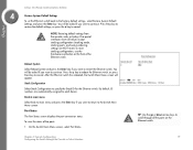
... unit LEDs. Chapter 3: Connecting the Switch 23 Configuring Units and Ports Displays the current Stacking Master. • Unit No. After Reset - Stack management is defined, and the device is powered on, but not operational. The LED status definitions are shown in the table below .) The unit is reset. 2. The switch is updated. Resetting the Unit to Factory Default Mode To reset the unit to Stack mode with a Unit ID of 0. LED Master ID n All ports Mode...
... unit LEDs. Chapter 3: Connecting the Switch 23 Configuring Units and Ports Displays the current Stacking Master. • Unit No. After Reset - Stack management is defined, and the device is powered on, but not operational. The LED status definitions are shown in the table below .) The unit is reset. 2. The switch is updated. Resetting the Unit to Factory Default Mode To reset the unit to Stack mode with a Unit ID of 0. LED Master ID n All ports Mode...
Administration Guide
Page 31
... the state it receives the same configuration as the Stack Master. Replacing a Failed Stack Master Unit in the following manner: • If a 24-port unit replaces a failed 48-port unit, the ports of the incoming unit are currently applied. For example, if the incoming unit is assigned the same Unit ID of the Chapter 3: Connecting the Switch 25 Stack Troubleshooting and Maintenance Chapter Linksys One...
... the state it receives the same configuration as the Stack Master. Replacing a Failed Stack Master Unit in the following manner: • If a 24-port unit replaces a failed 48-port unit, the ports of the incoming unit are currently applied. For example, if the incoming unit is assigned the same Unit ID of the Chapter 3: Connecting the Switch 25 Stack Troubleshooting and Maintenance Chapter Linksys One...

Administration Guide
Page 35
... in factory default mode, renumbering does not occur, and even a reset of the units will remain shut down until a master-enabled unit is selected as follows: Chapter 3: Connecting the Switch 29 Stack Troubleshooting and Maintenance Merging Two Stacks To merge two working stacks and create one of the two groups. If the incoming units are 3 through 8 in the "Building Automatically-Configured Stacks" or "Building Manually-Configured Stacks" sections...
... in factory default mode, renumbering does not occur, and even a reset of the units will remain shut down until a master-enabled unit is selected as follows: Chapter 3: Connecting the Switch 29 Stack Troubleshooting and Maintenance Merging Two Stacks To merge two working stacks and create one of the two groups. If the incoming units are 3 through 8 in the "Building Automatically-Configured Stacks" or "Building Manually-Configured Stacks" sections...

Administration Guide
Page 37
... the boot process, some of the stack that originally belonged to a running group of units is added to insert too many switches are shut down. Understanding Stacking Cable Failure If the stacking connection cables fail and cause a stack split, the scenario described in the stack, and no way to be connected and join the stack. A Stack Master is no changes are powered on at the same time...
... the boot process, some of the stack that originally belonged to a running group of units is added to insert too many switches are shut down. Understanding Stacking Cable Failure If the stacking connection cables fail and cause a stack split, the scenario described in the stack, and no way to be connected and join the stack. A Stack Master is no changes are powered on at the same time...

Administration Guide
Page 39
... listed in the next chapter. Then, click the OK button. Configuration can be performed through a telnet connection. This chapter describes console interface configuration. Chapter Linksys One Ready Communications Solution 4 Console Configuration Overview The Ethernet switch features a menu-based console interface for basic configuration of the Ethernet switch and management of connection is Linksys One. 5. NOTE: The Ethernet switch is setup by default to configure the HyperTerminal application on the default VLAN 100. Select Communications. 3. On the Connection...
... listed in the next chapter. Then, click the OK button. Configuration can be performed through a telnet connection. This chapter describes console interface configuration. Chapter Linksys One Ready Communications Solution 4 Console Configuration Overview The Ethernet switch features a menu-based console interface for basic configuration of the Ethernet switch and management of connection is Linksys One. 5. NOTE: The Ethernet switch is setup by default to configure the HyperTerminal application on the default VLAN 100. Select Communications. 3. On the Connection...

Administration Guide
Page 41
.... Configuring the Switch through a Windows command window. 2. Open a telnet session using Telnet or SSH Press the Enter key. Use your preferred Telnet or Secure Shell Client application, for example HyperTerminal or the Telnet application available through the Console or Telnet Interface The management screens consist of a series of menus. Chapter Linksys One Ready Communications Solution 4 Connecting to the Switch using Telnet or SSH If you know the IP address of your Ethernet switch (obtained from your DHCP server or...
.... Configuring the Switch through a Windows command window. 2. Open a telnet session using Telnet or SSH Press the Enter key. Use your preferred Telnet or Secure Shell Client application, for example HyperTerminal or the Telnet application available through the Console or Telnet Interface The management screens consist of a series of menus. Chapter Linksys One Ready Communications Solution 4 Connecting to the Switch using Telnet or SSH If you know the IP address of your Ethernet switch (obtained from your DHCP server or...

Administration Guide
Page 49
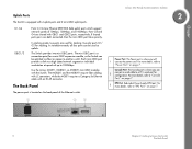
... an static IP address to be a DHCP client, then select ENABLE. The IP address of interface. IP Address Configuration (Layer 3) The IP information of the Ethernet switch is displayed. IP Address Subnet Mask Default Gateway Management VLAN DHCP client The IP Address of the Ethernet switch is displayed. Chapter Linksys One Ready Communications Solution 4 IP Configuration The IP Configuration screen displays these choices: the IP Address Settings, HTTP, HTTPS Configuration, and Network Configuration of the Ethernet switch. The VLAN ID number...
... an static IP address to be a DHCP client, then select ENABLE. The IP address of interface. IP Address Configuration (Layer 3) The IP information of the Ethernet switch is displayed. IP Address Subnet Mask Default Gateway Management VLAN DHCP client The IP Address of the Ethernet switch is displayed. Chapter Linksys One Ready Communications Solution 4 IP Configuration The IP Configuration screen displays these choices: the IP Address Settings, HTTP, HTTPS Configuration, and Network Configuration of the Ethernet switch. The VLAN ID number...

Administration Guide
Page 52
... Execute to upload or download files, such as the startup configuration, boot, or image file, using a TFTP server. File Management The File Management screen allows you copy an image to save your changes are two software images on the Ethernet switch: Image 1 and Image 2. When your changes. Linksys One Ready Communications Solution 4 46 Chapter 4: Console Configuration Configuring the Switch through the Console or Telnet Interface When you to upload or download the designated file. Chapter Select Edit...
... Execute to upload or download files, such as the startup configuration, boot, or image file, using a TFTP server. File Management The File Management screen allows you copy an image to save your changes are two software images on the Ethernet switch: Image 1 and Image 2. When your changes. Linksys One Ready Communications Solution 4 46 Chapter 4: Console Configuration Configuring the Switch through the Console or Telnet Interface When you to upload or download the designated file. Chapter Select Edit...
Administration Guide
Page 53
... view the status of the Ethernet switch. Chapter 4: Console Configuration Configuring the Switch through the Console or Telnet Interface TIP: Use the up or down arrow keys to scroll through all values except stacking configuration (stacking mode, stacking ports, and auto-numbering settings are automatically assigned to continue. To reset stacking configuration, use the hardware reset button on the Ethernet switch. 47 On the Switch Main Menu screen, select Port Status. Press the y key to reboot the Ethernet switch, or press the n key to specify the Stack ID for the Ethernet switch...
... view the status of the Ethernet switch. Chapter 4: Console Configuration Configuring the Switch through the Console or Telnet Interface TIP: Use the up or down arrow keys to scroll through all values except stacking configuration (stacking mode, stacking ports, and auto-numbering settings are automatically assigned to continue. To reset stacking configuration, use the hardware reset button on the Ethernet switch. 47 On the Switch Main Menu screen, select Port Status. Press the y key to reboot the Ethernet switch, or press the n key to specify the Stack ID for the Ethernet switch...
Administration Guide
Page 56
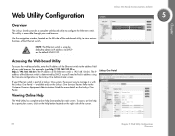
... setup by DHCP, so you'll need to view various functions of the Ethernet switch is 192.168.100.20. Refer to obtain its address using the Console configuration or the Linksys One Administrator screen. To access on-line help functionality for more details on the default VLAN 100. Viewing Online Help The Web Utility has complete online help for a particular screen, click on the Help button...
... setup by DHCP, so you'll need to view various functions of the Ethernet switch is 192.168.100.20. Refer to obtain its address using the Console configuration or the Linksys One Administrator screen. To access on-line help functionality for more details on the default VLAN 100. Viewing Online Help The Web Utility has complete online help for a particular screen, click on the Help button...
Administration Guide
Page 66
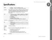
Specifications Models Standards Ports Cabling Type PoE Switching Capacity LEDs Stack Operation Buttons • SFE2000 - 24-port 10/100 Ethernet switch • SFE2000P - 24-port 10/100 Ethernet switch with PoE 802.3 10BASE-T Ethernet, 802.3u 100BASE-TX Fast Ethernet, 802.3ab 1000BASE-T Gigabit Ethernet, 802.3z Gigabit Ethernet, 802.3x Flow Control, 802.3ad LACP,802.3af POE, 802.1d STP, 802.1Q/p VLAN, 802.1w Rapid STP, 802.1s Multiple STP, 802.1x Port Access Authentication • 24 RJ-45 connectors for 10BASE-T/100BASE-TX...
Specifications Models Standards Ports Cabling Type PoE Switching Capacity LEDs Stack Operation Buttons • SFE2000 - 24-port 10/100 Ethernet switch • SFE2000P - 24-port 10/100 Ethernet switch with PoE 802.3 10BASE-T Ethernet, 802.3u 100BASE-TX Fast Ethernet, 802.3ab 1000BASE-T Gigabit Ethernet, 802.3z Gigabit Ethernet, 802.3x Flow Control, 802.3ad LACP,802.3af POE, 802.1d STP, 802.1Q/p VLAN, 802.1w Rapid STP, 802.1s Multiple STP, 802.1x Port Access Authentication • 24 RJ-45 connectors for 10BASE-T/100BASE-TX...


