
Hardware Installation Guide
Page 6
... DC Power Connector 1-21 Cisco RPS Connector 1-22 Console Port 1-23 2 C H A P T E R Installation 2-1 Preparing for Installation 2-1 Warnings 2-1 EMC Regulatory Statements 2-4 U.S.A. 2-4 Taiwan 2-4 Japan 2-5 Korea 2-5 Hungary 2-6 Installation Guidelines 2-6 Verifying Package Contents 2-7 Installing the Switch on a Table or Shelf 2-9 Installing the Switch in a Rack 2-9 Removing Screws from the Switch 2-11 Attaching the Brackets to a Catalyst 2912 XL, 2924C XL...
... DC Power Connector 1-21 Cisco RPS Connector 1-22 Console Port 1-23 2 C H A P T E R Installation 2-1 Preparing for Installation 2-1 Warnings 2-1 EMC Regulatory Statements 2-4 U.S.A. 2-4 Taiwan 2-4 Japan 2-5 Korea 2-5 Hungary 2-6 Installation Guidelines 2-6 Verifying Package Contents 2-7 Installing the Switch on a Table or Shelf 2-9 Installing the Switch in a Rack 2-9 Removing Screws from the Switch 2-11 Attaching the Brackets to a Catalyst 2912 XL, 2924C XL...

Hardware Installation Guide
Page 7
...18 Attaching the Optional Cable Guide 2-19 Installing the Switch on a Wall 2-20 Attaching the Brackets to the Switch 2-21 Mounting the Switch to a Wall 2-22 Powering On the Switch and Running POST 2-24 Connecting to DC Power 2-25 Preparing for Installation 2-25 Grounding the Switch 2-26 Wiring the DC-Input Power Source 2-29... Correcting Module POST Failures 3-2 Diagnosing Problems 3-3 Technical Specifications A-1 Connectors and Cable Specifications B-1 Connector Specifications B-1 10/100 Ports B-1 100BASE-FX Ports B-2 Contents 78-6461-04 Catalyst 2900 Series XL Hardware Installation Guide vii
...18 Attaching the Optional Cable Guide 2-19 Installing the Switch on a Wall 2-20 Attaching the Brackets to the Switch 2-21 Mounting the Switch to a Wall 2-22 Powering On the Switch and Running POST 2-24 Connecting to DC Power 2-25 Preparing for Installation 2-25 Grounding the Switch 2-26 Wiring the DC-Input Power Source 2-29... Correcting Module POST Failures 3-2 Diagnosing Problems 3-3 Technical Specifications A-1 Connectors and Cable Specifications B-1 Connector Specifications B-1 10/100 Ports B-1 100BASE-FX Ports B-2 Contents 78-6461-04 Catalyst 2900 Series XL Hardware Installation Guide vii

Hardware Installation Guide
Page 9
INDEX Class 1 Laser Product Warning C-22 Laser Beam Exposure Warning C-23 No On/Off Switch Warning C-24 Chassis Warning-Rack-Mounting and Servicing C-25 Reinforced Insulation Warning C-29 LAN Connections Only Warning C-30 No Field-Replaceable Units Warning C-31 Installation ... Equipment Warning C-36 Ground Connection Warning C-37 Qualified Personnel Warning C-38 DC Power Disconnection Warning C-39 Exposed Wire Lead Warning C-41 Contents 78-6461-04 Catalyst 2900 Series XL Hardware Installation Guide ix
INDEX Class 1 Laser Product Warning C-22 Laser Beam Exposure Warning C-23 No On/Off Switch Warning C-24 Chassis Warning-Rack-Mounting and Servicing C-25 Reinforced Insulation Warning C-29 LAN Connections Only Warning C-30 No Field-Replaceable Units Warning C-31 Installation ... Equipment Warning C-36 Ground Connection Warning C-37 Qualified Personnel Warning C-38 DC Power Disconnection Warning C-39 Exposed Wire Lead Warning C-41 Contents 78-6461-04 Catalyst 2900 Series XL Hardware Installation Guide ix

Hardware Installation Guide
Page 11
... Series XL Hardware Installation Guide xi Chapter 2, "Installation," provides the procedures for installing and configuring a Catalyst 2900 series XL switch. Purpose The Catalyst 2900 Series XL Hardware Installation Guide documents the hardware features of the switches, explains how to identify and resolve some of Ethernet and local area networking. It describes the physical and...
... Series XL Hardware Installation Guide xi Chapter 2, "Installation," provides the procedures for installing and configuring a Catalyst 2900 series XL switch. Purpose The Catalyst 2900 Series XL Hardware Installation Guide documents the hardware features of the switches, explains how to identify and resolve some of Ethernet and local area networking. It describes the physical and...

Hardware Installation Guide
Page 12
... and information: Command descriptions use these conventions: • Commands and keywords are in boldface. • Arguments for the switches and the regulatory agency approvals. In this manual. Conventions Preface Appendix A, "Technical Specifications," lists the physical and environmental specifications... C, "Translated Safety Warnings," provides translations in various languages of the warnings in equipment damage or loss of data. Catalyst 2900 Series XL Hardware Installation Guide xii 78-6461-04 Notes, cautions, and warnings use the following conventions to materials...
... and information: Command descriptions use these conventions: • Commands and keywords are in boldface. • Arguments for the switches and the regulatory agency approvals. In this manual. Conventions Preface Appendix A, "Technical Specifications," lists the physical and environmental specifications... C, "Translated Safety Warnings," provides translations in various languages of the warnings in equipment damage or loss of data. Catalyst 2900 Series XL Hardware Installation Guide xii 78-6461-04 Notes, cautions, and warnings use the following conventions to materials...

Hardware Installation Guide
Page 15
... xvi. • Release Notes for the Catalyst 2900 Series XL and Catalyst 3500 Series XL Switches (not orderable but is available on Cisco.com) Note Switch requirements and procedures for initial configurations and software upgrades tend to the release notes on Cisco.com for the latest information. 78-6461-04 Catalyst 2900 Series XL Hardware Installation Guide...
... xvi. • Release Notes for the Catalyst 2900 Series XL and Catalyst 3500 Series XL Switches (not orderable but is available on Cisco.com) Note Switch requirements and procedures for initial configurations and software upgrades tend to the release notes on Cisco.com for the latest information. 78-6461-04 Catalyst 2900 Series XL Hardware Installation Guide...

Hardware Installation Guide
Page 16
... online help (available only from the switch CMS software) • Catalyst 2900 Series XL Hardware Installation Guide (order number DOC-786461=) • Catalyst 3500 Series XL Hardware Installation Guide (order number DOC-786456=) • Catalyst 2900 Series XL Modules Installation Guide (order...1000BASE-T Gigabit Interface Converter Installation Note (not orderable but is available on Cisco.com) • Catalyst GigaStack Gigabit Interface Converter Hardware Installation Guide (order number DOC-786460=) • Cisco LRE CPE Hardware Installation Guide (order number DOC-7811469=) • ...
... online help (available only from the switch CMS software) • Catalyst 2900 Series XL Hardware Installation Guide (order number DOC-786461=) • Catalyst 3500 Series XL Hardware Installation Guide (order number DOC-786456=) • Catalyst 2900 Series XL Modules Installation Guide (order...1000BASE-T Gigabit Interface Converter Installation Note (not orderable but is available on Cisco.com) • Catalyst GigaStack Gigabit Interface Converter Hardware Installation Guide (order number DOC-786460=) • Cisco LRE CPE Hardware Installation Guide (order number DOC-7811469=) • ...

Hardware Installation Guide
Page 21
..., Cisco IP Phones, and other network devices such as backbone switches, aggregating 10/100 and Gigabit Ethernet traffic from other switches. The 2900 XL LRE switches employ Long-Reach Ethernet (LRE), a very-high-data-rate digital subscriber line (VDSL)-based technology that describe the Catalyst 2900 series XL switches, hereafter referred to as the switches. • Switch features...
..., Cisco IP Phones, and other network devices such as backbone switches, aggregating 10/100 and Gigabit Ethernet traffic from other switches. The 2900 XL LRE switches employ Long-Reach Ethernet (LRE), a very-high-data-rate digital subscriber line (VDSL)-based technology that describe the Catalyst 2900 series XL switches, hereafter referred to as the switches. • Switch features...

Hardware Installation Guide
Page 22
... • On the Catalyst 2912 LRE XL and 2924 LRE XL switches, up to 24 LRE ports through one RJ-21 connector and hot swapping capability with the Cisco LRE customer premises equipment (CPE) devices • Supports up to 2048 MAC addresses on the Catalyst 2924 XL, 2924C XL..., and 2912 XL switches • Supports up to 8192 MAC addresses on the Catalyst 2924M XL, Catalyst 2924M XL DC and Catalyst 2912MF XL switches Figure 1-1 shows the switch models. Catalyst ...
... • On the Catalyst 2912 LRE XL and 2924 LRE XL switches, up to 24 LRE ports through one RJ-21 connector and hot swapping capability with the Cisco LRE customer premises equipment (CPE) devices • Supports up to 2048 MAC addresses on the Catalyst 2924 XL, 2924C XL..., and 2912 XL switches • Supports up to 8192 MAC addresses on the Catalyst 2924M XL, Catalyst 2924M XL DC and Catalyst 2912MF XL switches Figure 1-1 shows the switch models. Catalyst ...

Hardware Installation Guide
Page 23
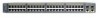
Chapter 1 Product Overview Figure 1-1 Catalyst 2900 Series XL Switches Version Number Description WS-C2912-LRE-XL 4 fixed autosensing 10/100 ports INPUT OUTPUT PWR PWR RESET TEMP FAN 9X 10X 11X 12X 12 LRE ports Cisco RPS 300 WS-C2924-LRE-XL 4 fixed autosensing 10/100 ports 24 LRE ports INPUT OUTPUT PWR PWR... 4 5 100BASE-FX 6 7 8 9 10 11 12 WS-C2924M-XL WS-C2924M-XLEM-DC 24 fixed autosensing 10/100 ports 2 expansion slots 12 MODE 1X 2X 3X Catalyst 2900 SERIES XL 4X 5X 6X 7X 8X 9X 10X 11X 100BaseFX 12X 13X 14X 15X 16X 17X 18X 19X 20X 21X 22X 23X 24X...
Chapter 1 Product Overview Figure 1-1 Catalyst 2900 Series XL Switches Version Number Description WS-C2912-LRE-XL 4 fixed autosensing 10/100 ports INPUT OUTPUT PWR PWR RESET TEMP FAN 9X 10X 11X 12X 12 LRE ports Cisco RPS 300 WS-C2924-LRE-XL 4 fixed autosensing 10/100 ports 24 LRE ports INPUT OUTPUT PWR PWR... 4 5 100BASE-FX 6 7 8 9 10 11 12 WS-C2924M-XL WS-C2924M-XLEM-DC 24 fixed autosensing 10/100 ports 2 expansion slots 12 MODE 1X 2X 3X Catalyst 2900 SERIES XL 4X 5X 6X 7X 8X 9X 10X 11X 100BaseFX 12X 13X 14X 15X 16X 17X 18X 19X 20X 21X 22X 23X 24X...

Hardware Installation Guide
Page 24
... network management protocol (SNMP)-SNMP provides a means to monitor and control the switch and switch cluster members. For more information about CMS, the CLI, and SNMP refer to the Catalyst 2900 Series XL and Catalyst 3500 Series XL Software Configuration Guide. Catalyst 2900 Series XL Hardware Installation Guide 1-4 78-6461-04 CMS is running platforms...
... network management protocol (SNMP)-SNMP provides a means to monitor and control the switch and switch cluster members. For more information about CMS, the CLI, and SNMP refer to the Catalyst 2900 Series XL and Catalyst 3500 Series XL Software Configuration Guide. Catalyst 2900 Series XL Hardware Installation Guide 1-4 78-6461-04 CMS is running platforms...

Hardware Installation Guide
Page 26
... Note A Category 5 cable is a straight-through, twisted-pair cable. The 10/100 switch ports can use a crossover cable. Refer to the Catalyst 2900 Series XL and Catalyst 3500 Series XL Software Configuration Guide for Cisco IP Phones and per-port priority override. Catalyst 2900 Series XL Hardware Installation Guide 1-6 78-6461-04 When connecting the...
... Note A Category 5 cable is a straight-through, twisted-pair cable. The 10/100 switch ports can use a crossover cable. Refer to the Catalyst 2900 Series XL and Catalyst 3500 Series XL Software Configuration Guide for Cisco IP Phones and per-port priority override. Catalyst 2900 Series XL Hardware Installation Guide 1-6 78-6461-04 When connecting the...

Hardware Installation Guide
Page 27
... for half-duplex operation, the connection can be connected to the Catalyst 2900 Series XL and Catalyst 3500 Series XL Software Configuration Guide. For more information about configuring the LRE ports, refer to the patch panel through a private branch exchange (PBX) switch, a Cisco LRE 48 POTS Splitter can be over distances of up to...
... for half-duplex operation, the connection can be connected to the Catalyst 2900 Series XL and Catalyst 3500 Series XL Software Configuration Guide. For more information about configuring the LRE ports, refer to the patch panel through a private branch exchange (PBX) switch, a Cisco LRE 48 POTS Splitter can be over distances of up to...

Hardware Installation Guide
Page 28
... required, a splitter is not needed, and the switch can connect directly to other switch ports and is internally switched to the patch panel. Note Cisco Long-Reach Ethernet (LRE) products are for the Cisco LRE 48 POTS Splitter. Digital telephones connected to the Installation Notes for the Catalyst 2900 XL hot-swappable modules. For more information...
... required, a splitter is not needed, and the switch can connect directly to other switch ports and is internally switched to the patch panel. Note Cisco Long-Reach Ethernet (LRE) products are for the Cisco LRE 48 POTS Splitter. Digital telephones connected to the Installation Notes for the Catalyst 2900 XL hot-swappable modules. For more information...

Hardware Installation Guide
Page 29
...the LEDs and the Mode button that you insert them in a 2924M XL or Catalyst 2912MF XL switch (both supporting 8192 MAC addresses), the module fails POST. After the restart, the switch address capacity is working properly before it starts forwarding packets. For a complete list and... Guide for detailed information on self-test (POST) verifies that switch. A power-on expansion modules for the Catalyst 2900 Series XL and Catalyst 3500 Series XL Switches. Refer to the Release Notes for Catalyst 2900 series XL switches. LEDs 78-6461-04 You can start the module by each...
...the LEDs and the Mode button that you insert them in a 2924M XL or Catalyst 2912MF XL switch (both supporting 8192 MAC addresses), the module fails POST. After the restart, the switch address capacity is working properly before it starts forwarding packets. For a complete list and... Guide for detailed information on self-test (POST) verifies that switch. A power-on expansion modules for the Catalyst 2900 Series XL and Catalyst 3500 Series XL Switches. Refer to the Release Notes for Catalyst 2900 series XL switches. LEDs 78-6461-04 You can start the module by each...

Hardware Installation Guide
Page 30
... Series XL and Catalyst 3500 Series XL Software Configuration Guide describes how to use CMS to manage standalone or individual switches and how to use cluster management software to manage switch clusters]. Front-Panel Description Chapter 1 Product Overview All of the LEDs described in this section except the ...utilization meter (UTL) are visible on the Cluster Management Suite (CMS) window and, if the switch is a cluster member, on the CMS Cluster Manager window. Figure 1-5 Catalyst 2912 XL, 2924 XL, and 2924C XL LEDs 10/100 port LEDs System LED Port mode LEDs MODE ...
... Series XL and Catalyst 3500 Series XL Software Configuration Guide describes how to use CMS to manage standalone or individual switches and how to use cluster management software to manage switch clusters]. Front-Panel Description Chapter 1 Product Overview All of the LEDs described in this section except the ...utilization meter (UTL) are visible on the Cluster Management Suite (CMS) window and, if the switch is a cluster member, on the CMS Cluster Manager window. Figure 1-5 Catalyst 2912 XL, 2924 XL, and 2924C XL LEDs 10/100 port LEDs System LED Port mode LEDs MODE ...

Hardware Installation Guide
Page 32
Table 1-2 lists the LED colors and their meanings. Front-Panel Description Figure 1-7 Catalyst 2912 LRE XL and 2924 LRE XL LEDs 10/100 port LEDs Chapter 1 Product Overview SYSTEM RPS MODE LRE STAT DUPLX SPEED Mode button 1X .... System is receiving power and functioning properly. For information on the System LED colors during POST, see the "Powering On the Switch and Running POST" section on page 2-24. 1-12 Catalyst 2900 Series XL Hardware Installation Guide 78-6461-04 System is receiving power but is not powered up. Table 1-2 System LED...
Table 1-2 lists the LED colors and their meanings. Front-Panel Description Figure 1-7 Catalyst 2912 LRE XL and 2924 LRE XL LEDs 10/100 port LEDs Chapter 1 Product Overview SYSTEM RPS MODE LRE STAT DUPLX SPEED Mode button 1X .... System is receiving power and functioning properly. For information on the System LED colors during POST, see the "Powering On the Switch and Running POST" section on page 2-24. 1-12 Catalyst 2900 Series XL Hardware Installation Guide 78-6461-04 System is receiving power but is not powered up. Table 1-2 System LED...

Hardware Installation Guide
Page 33
... up power, if required. Chapter 1 Product Overview Front-Panel Description RPS LED The Catalyst 2912 LRE XL and Catalyst 2924 LRE XL switches use the Cisco RPS 600 (model PWR600-AC-RPS). All other Catalyst 2900 XL and Catalyst 3500 XL switches use the Cisco RPS 300 (model PWR300-AC-RPS-N1). RPS is off or not properly...
... up power, if required. Chapter 1 Product Overview Front-Panel Description RPS LED The Catalyst 2912 LRE XL and Catalyst 2924 LRE XL switches use the Cisco RPS 600 (model PWR600-AC-RPS). All other Catalyst 2900 XL and Catalyst 3500 XL switches use the Cisco RPS 300 (model PWR300-AC-RPS-N1). RPS is off or not properly...

Hardware Installation Guide
Page 34
Contact Cisco Systems. The internal power supply in use by the switch. (See Figure 1-8.) The port duplex mode: full duplex or half duplex, and default modes: • 10/100 ports: auto • 100BaseFX ports: auto • Gigabit ports: auto The port operating speed: 10 or 100 Mbps. 1-14 Catalyst 2900 Series ...and module slots have failed. Press the Standby/Active button on the Catalyst 2912 XL, 2924C XL, 2924 XL, 2924MF XL, 2924M XL, and 2924M XL DC Switches Mode LED STAT UTL FDUP 100 Port Mode Port status Switch utilization Port duplex mode Port speed Description The port status. If ...
Contact Cisco Systems. The internal power supply in use by the switch. (See Figure 1-8.) The port duplex mode: full duplex or half duplex, and default modes: • 10/100 ports: auto • 100BaseFX ports: auto • Gigabit ports: auto The port operating speed: 10 or 100 Mbps. 1-14 Catalyst 2900 Series ...and module slots have failed. Press the Standby/Active button on the Catalyst 2912 XL, 2924C XL, 2924 XL, 2924MF XL, 2924M XL, and 2924M XL DC Switches Mode LED STAT UTL FDUP 100 Port Mode Port status Switch utilization Port duplex mode Port speed Description The port status. If ...

Hardware Installation Guide
Page 35
... show Ethernet link status. Ethernet link status of the LRE ports on the Catalyst 2912 LRE XL and Catalyst 2924 LRE XL switches. Default mode on all Catalyst 2900 XL and Catalyst 3500 XL switches except the Catalyst 2912 LRE XL and Catalyst 2924 LRE XL switches. The port duplex mode: full duplex or half duplex. Default mode on...
... show Ethernet link status. Ethernet link status of the LRE ports on the Catalyst 2912 LRE XL and Catalyst 2924 LRE XL switches. Default mode on all Catalyst 2900 XL and Catalyst 3500 XL switches except the Catalyst 2912 LRE XL and Catalyst 2924 LRE XL switches. The port duplex mode: full duplex or half duplex. Default mode on...


