
Hardware Installation Guide
Page 2
...specifications are designed to provide reasonable protection against such interference in the document are service marks; The Cisco implementation of this manual generates and may radiate radio-frequency energy. All other company. (1002R) Any Internet Protocol (IP) addresses used in a commercial environment. Catalyst 2960 Switch... Hardware Installation Guide © 2005-2010 Cisco Systems, Inc. These limits are designed to comply with the limits for illustrative ...
...specifications are designed to provide reasonable protection against such interference in the document are service marks; The Cisco implementation of this manual generates and may radiate radio-frequency energy. All other company. (1002R) Any Internet Protocol (IP) addresses used in a commercial environment. Catalyst 2960 Switch... Hardware Installation Guide © 2005-2010 Cisco Systems, Inc. These limits are designed to comply with the limits for illustrative ...

Hardware Installation Guide
Page 5
... 3-18 Troubleshooting 4-1 Diagnosing Problems 4-1 Verify Switch POST Results 4-2 Monitor Switch LEDs 4-2 Verify Switch Connections 4-2 Bad or Damaged Cable 4-2 Ethernet...Switch Performance 4-4 Speed, Duplex, and Autonegotiation 4-4 Autonegotiation and NIC Cards 4-5 Cabling Distance 4-5 Clearing the Switch IP Address and Configuration 4-5 Locating the Switch Serial Number 4-6 Technical Specifications A-1 Connector and Cable Specifications B-1 Connector Specifications B-1 10/100/1000 Ports B-1 Connecting to 1000BASE-T Devices B-2 SFP Module Ports B-3 Dual-Purpose Ports B-3 Catalyst 2960 Switch...
... 3-18 Troubleshooting 4-1 Diagnosing Problems 4-1 Verify Switch POST Results 4-2 Monitor Switch LEDs 4-2 Verify Switch Connections 4-2 Bad or Damaged Cable 4-2 Ethernet...Switch Performance 4-4 Speed, Duplex, and Autonegotiation 4-4 Autonegotiation and NIC Cards 4-5 Cabling Distance 4-5 Clearing the Switch IP Address and Configuration 4-5 Locating the Switch Serial Number 4-6 Technical Specifications A-1 Connector and Cable Specifications B-1 Connector Specifications B-1 10/100/1000 Ports B-1 Connecting to 1000BASE-T Devices B-2 SFP Module Ports B-3 Dual-Purpose Ports B-3 Catalyst 2960 Switch...

Hardware Installation Guide
Page 6
... E N D I X INDEX Console Port B-4 Cable and Adapter Specifications B-4 SFP Module Cable Specifications B-4 Two Twisted-Pair Cable Pinouts B-6 Four Twisted-Pair Cable Pinouts for 1000BASE-T Ports B-6 Crossover Cable and Adapter Pinouts B-7 Identifying a Crossover Cable B-7 Adapter Pinouts B-8 Configuring the Switch with the CLI-Based Setup Program C-1 Accessing the CLI C-1 Accessing ... Software C-3 Connecting to a Power Source C-4 Entering the Initial Configuration Information C-4 IP Settings C-5 Completing the Setup Program C-5 Catalyst 2960 Switch Hardware Installation Guide vi OL-7075-09
... E N D I X INDEX Console Port B-4 Cable and Adapter Specifications B-4 SFP Module Cable Specifications B-4 Two Twisted-Pair Cable Pinouts B-6 Four Twisted-Pair Cable Pinouts for 1000BASE-T Ports B-6 Crossover Cable and Adapter Pinouts B-7 Identifying a Crossover Cable B-7 Adapter Pinouts B-8 Configuring the Switch with the CLI-Based Setup Program C-1 Accessing the CLI C-1 Accessing ... Software C-3 Connecting to a Power Source C-4 Entering the Initial Configuration Information C-4 IP Settings C-5 Completing the Setup Program C-5 Catalyst 2960 Switch Hardware Installation Guide vi OL-7075-09

Hardware Installation Guide
Page 13
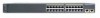
...; Catalyst 2960-8TC-L • Catalyst 2960G-8TC-L • Catalyst 2960-8TC-S • Catalyst 2960PD-8TT-L • Catalyst 2960-24-S • Catalyst 2960-24TC-S • Catalyst 2960-48TT-S • Catalyst 2960-48TC-S OL-7075-09 Catalyst 2960 Switch Hardware Installation Guide 1-3 See the compatibility matrix documents for the RPS systems on Cisco.com for an optional Cisco RPS 2300 or Cisco RPS 675 redundant power system that operates on specific switches, see the Cisco...
...; Catalyst 2960-8TC-L • Catalyst 2960G-8TC-L • Catalyst 2960-8TC-S • Catalyst 2960PD-8TT-L • Catalyst 2960-24-S • Catalyst 2960-24TC-S • Catalyst 2960-48TT-S • Catalyst 2960-48TC-S OL-7075-09 Catalyst 2960 Switch Hardware Installation Guide 1-3 See the compatibility matrix documents for the RPS systems on Cisco.com for an optional Cisco RPS 2300 or Cisco RPS 675 redundant power system that operates on specific switches, see the Cisco...

Hardware Installation Guide
Page 21
...set the 10/100/1000 ports to autonegotiate, it senses the speed and duplex settings of the connection. OL-7075-09 Catalyst 2960 Switch Hardware Installation Guide 1-11 When the port is , the fastest line speed that both devices support and full-duplex transmission if...10/100/1000 Ports You can use the mdix auto interface configuration command in Appendix B, "Connector and Cable Specifications." When you connect the switch to workstations, servers, routers, and Cisco IP Phones, be sure to enable the automatic medium-dependent interface crossover (auto-MDIX) feature. You can ...
...set the 10/100/1000 ports to autonegotiate, it senses the speed and duplex settings of the connection. OL-7075-09 Catalyst 2960 Switch Hardware Installation Guide 1-11 When the port is , the fastest line speed that both devices support and full-duplex transmission if...10/100/1000 Ports You can use the mdix auto interface configuration command in Appendix B, "Connector and Cable Specifications." When you connect the switch to workstations, servers, routers, and Cisco IP Phones, be sure to enable the automatic medium-dependent interface crossover (auto-MDIX) feature. You can ...

Hardware Installation Guide
Page 23
..."Connector and Cable Specifications." You use Category 5 or higher cable with LC connectors to connect to a fiber-optic SFP module. By default, the switch dynamically selects the ...Catalyst 2960 switches (other than those listed) use Gigabit Ethernet SFP modules for Gigabit uplink connections and 100-Megabit SFP modules for Gigabit uplink connections to other switches. These Catalyst 2960 switches do not have an SFP module slot: • Catalyst 2960PD-8TT-L • Catalyst 2960-24LT-L • Catalyst 2960-24-S • Catalyst 2960-24TT-L • Catalyst 2960-48TT-L • Catalyst 2960...
..."Connector and Cable Specifications." You use Category 5 or higher cable with LC connectors to connect to a fiber-optic SFP module. By default, the switch dynamically selects the ...Catalyst 2960 switches (other than those listed) use Gigabit Ethernet SFP modules for Gigabit uplink connections and 100-Megabit SFP modules for Gigabit uplink connections to other switches. These Catalyst 2960 switches do not have an SFP module slot: • Catalyst 2960PD-8TT-L • Catalyst 2960-24LT-L • Catalyst 2960-24-S • Catalyst 2960-24TT-L • Catalyst 2960-48TT-L • Catalyst 2960...

Hardware Installation Guide
Page 31
..."Connector and Cable Specifications" section on a left and right side panels. Figure 1-26 shows the slot on page B-1. Chapter 1 Product Overview Rear Panel Description • List the connected switches and the power-supply module sizes • Obtain reports when a switch is powered by ...The total maximum output power is a redundant power system that adapter from Cisco. Figure 1-26 Switch Left Panel 204628 1 1 Security slot OL-7075-09 Catalyst 2960 Switch Hardware Installation Guide 1-21 You can connect the switch to a PC by the RPS • Obtain status reports for the...
..."Connector and Cable Specifications" section on a left and right side panels. Figure 1-26 shows the slot on page B-1. Chapter 1 Product Overview Rear Panel Description • List the connected switches and the power-supply module sizes • Obtain reports when a switch is powered by ...The total maximum output power is a redundant power system that adapter from Cisco. Figure 1-26 Switch Left Panel 204628 1 1 Security slot OL-7075-09 Catalyst 2960 Switch Hardware Installation Guide 1-21 You can connect the switch to a PC by the RPS • Obtain status reports for the...

Hardware Installation Guide
Page 36
...Catalyst 2960 switches except for the Catalyst 2960-8TC-L, 2960-8TC-S, 2960G-8TC-L, and 2960PD-8TT-L switches. Statement 1046 Warning Voltages that present a shock hazard may exist on page B-5, which can be no longer than 328 feet (100 meters). • The cables meet the specifications...from construction activities). Catalyst 2960 Switch Hardware Installation Guide 2-4 OL-7075-09 These standards provide guidelines for Particulate Matter Cisco Ethernet switches are equipped with local and national electrical codes. Preparing for the Catalyst 2960 switch. Statement 1074 ...
...Catalyst 2960 switches except for the Catalyst 2960-8TC-L, 2960-8TC-S, 2960G-8TC-L, and 2960PD-8TT-L switches. Statement 1046 Warning Voltages that present a shock hazard may exist on page B-5, which can be no longer than 328 feet (100 meters). • The cables meet the specifications...from construction activities). Catalyst 2960 Switch Hardware Installation Guide 2-4 OL-7075-09 These standards provide guidelines for Particulate Matter Cisco Ethernet switches are equipped with local and national electrical codes. Preparing for the Catalyst 2960 switch. Statement 1074 ...

Hardware Installation Guide
Page 37
... listed in a rack, on a wall, or on Cisco.com describes the box contents. OL-7075-09 Catalyst 2960 Switch Hardware Installation Guide 2-5 You can easily read the front-panel indicators. - Box Contents The switch getting started guide on a table or shelf, you might...Note When you install the switch in Appendix A, "Technical Specifications." • Clearance to ports is safely away from sources of the power cord to active mode during normal operation. See Chapter 3, "Switch Installation (8-Port Switches)," and see the Cisco RPS documentation for unrestricted cabling...
... listed in a rack, on a wall, or on Cisco.com describes the box contents. OL-7075-09 Catalyst 2960 Switch Hardware Installation Guide 2-5 You can easily read the front-panel indicators. - Box Contents The switch getting started guide on a table or shelf, you might...Note When you install the switch in Appendix A, "Technical Specifications." • Clearance to ports is safely away from sources of the power cord to active mode during normal operation. See Chapter 3, "Switch Installation (8-Port Switches)," and see the Cisco RPS documentation for unrestricted cabling...

Hardware Installation Guide
Page 38
... that the switch functions properly. Call Cisco technical support representative if your specific switch; Installing the Switch Chapter 2 Switch Installation (24- and 48-Port Switches) Warning Attach...switches, see Chapter 3, "Switch Installation (8-Port Switches)." and 48-port switches. Warning To prevent bodily injury when mounting or servicing this unit in the "Installing the Switch" section on , it is the only unit in the rack. The following Cisco RPS model to those switches, see Chapter 3, "Switch Installation (8-Port Switches)." Statement 1006 Catalyst 2960 Switch...
... that the switch functions properly. Call Cisco technical support representative if your specific switch; Installing the Switch Chapter 2 Switch Installation (24- and 48-Port Switches) Warning Attach...switches, see Chapter 3, "Switch Installation (8-Port Switches)." and 48-port switches. Warning To prevent bodily injury when mounting or servicing this unit in the "Installing the Switch" section on , it is the only unit in the rack. The following Cisco RPS model to those switches, see Chapter 3, "Switch Installation (8-Port Switches)." Statement 1006 Catalyst 2960 Switch...

Hardware Installation Guide
Page 47
...," for solutions to the Catalyst 2960 switch release notes for reliable communications. Repeat Steps 1 through cable to an RJ-45 connector on the front panel. (See Figure 2-13.) When connecting to switches or repeaters, use a crossover cable. (See the "Cable and Adapter Specifications" section on page B-4 for...or a problem with the adapter installed in SFP module slots on when both the switch and the connected device have established link. Step 1 When connecting to workstations, servers, routers, and Cisco IP Phones, connect a straight-through 3 to use any combination of the same...
...," for solutions to the Catalyst 2960 switch release notes for reliable communications. Repeat Steps 1 through cable to an RJ-45 connector on the front panel. (See Figure 2-13.) When connecting to switches or repeaters, use a crossover cable. (See the "Cable and Adapter Specifications" section on page B-4 for...or a problem with the adapter installed in SFP module slots on when both the switch and the connected device have established link. Step 1 When connecting to workstations, servers, routers, and Cisco IP Phones, connect a straight-through 3 to use any combination of the same...
Hardware Installation Guide
Page 50
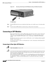
...SFP module, be sure that you are ready to Fiber-Optic SFP Modules" section. For instructions on the SFP module. 2-18 Catalyst 2960 Switch Hardware Installation Guide OL-7075-09 Statement 1008 Caution Do not remove the rubber plugs from the SFP module port or the rubber caps... Connecting to 1000BASE-T SFP Modules" section. See Appendix B, "Connector and Cable Specifications" for information about how to install or remove an SFP module, see the "Connecting to connect the cable. and 48-Port Switches) Figure 2-16 Removing a Bale-Clasp Latch SFP Module by Using a Flat-Blade...
...SFP module, be sure that you are ready to Fiber-Optic SFP Modules" section. For instructions on the SFP module. 2-18 Catalyst 2960 Switch Hardware Installation Guide OL-7075-09 Statement 1008 Caution Do not remove the rubber plugs from the SFP module port or the rubber caps... Connecting to 1000BASE-T SFP Modules" section. See Appendix B, "Connector and Cable Specifications" for information about how to install or remove an SFP module, see the "Connecting to connect the cable. and 48-Port Switches) Figure 2-16 Removing a Bale-Clasp Latch SFP Module by Using a Flat-Blade...

Hardware Installation Guide
Page 55
The installation information in this chapter is specific to the Catalyst 2960-8TC-S, Catalyst 2960-8TC-L, Catalyst 2960G-8TC-L, and Catalyst 2960PD-8TT-L switches. 3 C H A P T E R Switch Installation (8-Port Switches) This chapter describes how to start your switch and how to interpret the power-on self-test (POST) that exceeds the maximum recommended ambient temperature of clearance around the ventilation openings. Read the ...
The installation information in this chapter is specific to the Catalyst 2960-8TC-S, Catalyst 2960-8TC-L, Catalyst 2960G-8TC-L, and Catalyst 2960PD-8TT-L switches. 3 C H A P T E R Switch Installation (8-Port Switches) This chapter describes how to start your switch and how to interpret the power-on self-test (POST) that exceeds the maximum recommended ambient temperature of clearance around the ventilation openings. Read the ...

Hardware Installation Guide
Page 57
... For connections outside the building where the equipment is installed, the following ports must be unrestricted. OL-7075-09 Catalyst 2960 Switch Hardware Installation Guide 3-3 Contact the appropriate electrical inspection authority or an electrician if you are uncertain that exceeds normal ...national electrical codes. When you allow at its maximum temperature 113°F (45°C) and is specific to the other Catalyst 2960 switches, see Chapter 2, "Switch Installation (24- Statement 1073 Warning Installation of the equipment must always be made first and disconnected last...
... For connections outside the building where the equipment is installed, the following ports must be unrestricted. OL-7075-09 Catalyst 2960 Switch Hardware Installation Guide 3-3 Contact the appropriate electrical inspection authority or an electrician if you are uncertain that exceeds normal ...national electrical codes. When you allow at its maximum temperature 113°F (45°C) and is specific to the other Catalyst 2960 switches, see Chapter 2, "Switch Installation (24- Statement 1073 Warning Installation of the equipment must always be made first and disconnected last...

Hardware Installation Guide
Page 58
... switches other Catalyst 2960 switches, see Chapter 2, "Switch Installation (24- and 48-Port Switches)." To order a cable guard, contact your Cisco representative and use these conditions - The switch has security slots in the link to the Catalyst 2960 8-port switches. Cable locks are separated on the switch rear panel. • Cabling is away from most computer accessory suppliers. Access to ports is specific...
... switches other Catalyst 2960 switches, see Chapter 2, "Switch Installation (24- and 48-Port Switches)." To order a cable guard, contact your Cisco representative and use these conditions - The switch has security slots in the link to the Catalyst 2960 8-port switches. Cable locks are separated on the switch rear panel. • Cabling is away from most computer accessory suppliers. Access to ports is specific...

Hardware Installation Guide
Page 59
...Switch" section on Cisco.com describes the box contents. You can receive power from the switch. If a switch fails POST, the System LED turns amber. This section describes these installation procedures: • Desk- Chapter 3 Switch Installation (8-Port Switches) Verifying Switch Operation Installing the Catalyst 2960 8-port switches... in a 19-inch rack requires an optional bracket kit that the switch functions properly. The kit part number is specific to ...
...Switch" section on Cisco.com describes the box contents. You can receive power from the switch. If a switch fails POST, the System LED turns amber. This section describes these installation procedures: • Desk- Chapter 3 Switch Installation (8-Port Switches) Verifying Switch Operation Installing the Catalyst 2960 8-port switches... in a 19-inch rack requires an optional bracket kit that the switch functions properly. The kit part number is specific to ...

Hardware Installation Guide
Page 60
...the other . For information applicable to the front-panel ports. Doing so helps prevent airflow restriction and overheating. Catalyst 2960 Switch Hardware Installation Guide 3-6 OL-7075-09 See the switch getting started guide for instructions. 3. or Shelf-Mounting (with Mounting Screws), page 3-8 • Wall-Mounting...mounting screws. Do not stack switches or place switches side-by at least 3 inches (7.6 cm) of the unit. After the switch is specific to a 10/100 or 10/100/1000 port, and run Express Setup. Connect to the Catalyst 2960 8-port switches. If you do these ...
...the other . For information applicable to the front-panel ports. Doing so helps prevent airflow restriction and overheating. Catalyst 2960 Switch Hardware Installation Guide 3-6 OL-7075-09 See the switch getting started guide for instructions. 3. or Shelf-Mounting (with Mounting Screws), page 3-8 • Wall-Mounting...mounting screws. Do not stack switches or place switches side-by at least 3 inches (7.6 cm) of the unit. After the switch is specific to a 10/100 or 10/100/1000 port, and run Express Setup. Connect to the Catalyst 2960 8-port switches. If you do these ...
Hardware Installation Guide
Page 61
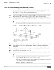
...Step 6 Step 7 Peel the adhesive strip off the bottom of the desk or shelf after the switch is specific to the desk or shelf. Place the switch onto the mounting screws, and slide the switch forward until they are separated on top of the desk or shelf so that the power cord ... screw template on all sides with mounting screws. Insert three screws in the three screw template slots. OL-7075-09 Catalyst 2960 Switch Hardware Installation Guide 3-7 Do not stack switches or place switches side-by -side slots face the front of the desk or shelf, as a guide to a desk or shelf ...
...Step 6 Step 7 Peel the adhesive strip off the bottom of the desk or shelf after the switch is specific to the desk or shelf. Place the switch onto the mounting screws, and slide the switch forward until they are separated on top of the desk or shelf so that the power cord ... screw template on all sides with mounting screws. Insert three screws in the three screw template slots. OL-7075-09 Catalyst 2960 Switch Hardware Installation Guide 3-7 Do not stack switches or place switches side-by -side slots face the front of the desk or shelf, as a guide to a desk or shelf ...
Hardware Installation Guide
Page 62
... Peel the adhesive strip off the bottom of the screw template, and attach it to the front-panel ports. See the switch getting started guide for instructions. 3. Catalyst 2960 Switch Hardware Installation Guide 3-8 OL-7075-09 See the "Connecting to the 10/100 and 10/100/1000 Ports" section on... is used to align the mounting screw holes and is specific to a 10/100 or 10/100/1000 port, and run Express Setup. Connect to the Catalyst 2960 8-port switches. or Shelf-Mounting (with proper clearance. and 48-Port Switches)." Position the screw template underneath the desk or shelf so...
... Peel the adhesive strip off the bottom of the screw template, and attach it to the front-panel ports. See the switch getting started guide for instructions. 3. Catalyst 2960 Switch Hardware Installation Guide 3-8 OL-7075-09 See the "Connecting to the 10/100 and 10/100/1000 Ports" section on... is used to align the mounting screw holes and is specific to a 10/100 or 10/100/1000 port, and run Express Setup. Connect to the Catalyst 2960 8-port switches. or Shelf-Mounting (with proper clearance. and 48-Port Switches)." Position the screw template underneath the desk or shelf so...
Hardware Installation Guide
Page 65
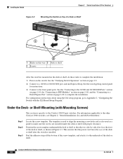
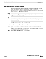
... information applicable to the system. Statement 378 Note Do not wall-mount the switch with Mounting Screws) This section is used to the Catalyst 2960 8-port switches. The template is specific to align the mounting screw holes. Chapter 3 Switch Installation (8-Port Switches) Installing the Switch Wall-Mounting (with its front panel facing down (as shown in Figure 3-5. According...
... information applicable to the system. Statement 378 Note Do not wall-mount the switch with Mounting Screws) This section is used to the Catalyst 2960 8-port switches. The template is specific to align the mounting screw holes. Chapter 3 Switch Installation (8-Port Switches) Installing the Switch Wall-Mounting (with its front panel facing down (as shown in Figure 3-5. According...
