
Hardware Installation Guide
Page 5
... 4-1 Verify Switch POST Results 4-2 Monitor Switch LEDs 4-2 Verify Switch Connections 4-2 Bad or Damaged Cable 4-2 Ethernet and Fiber Cables 4-3 Link Status 4-3 Transceiver Module Port Issues 4-3 Port and Interface Settings 4-4 Ping the End Device 4-4 Spanning Tree Loops 4-4 Monitor Switch Performance 4-4 Speed... B-3 Dual-Purpose Ports B-3 Catalyst 2960 Switch Hardware Installation Guide v or Shelf-Mounting (with Mounting Screws) 3-8 Wall-Mounting (with Mounting Screws) 3-11 Magnet Mounting 3-14 Rack-Mounting 3-15 Attaching Brackets to the Switch 3-15 Mounting the Switch in a 19-Inch Rack...
... 4-1 Verify Switch POST Results 4-2 Monitor Switch LEDs 4-2 Verify Switch Connections 4-2 Bad or Damaged Cable 4-2 Ethernet and Fiber Cables 4-3 Link Status 4-3 Transceiver Module Port Issues 4-3 Port and Interface Settings 4-4 Ping the End Device 4-4 Spanning Tree Loops 4-4 Monitor Switch Performance 4-4 Speed... B-3 Dual-Purpose Ports B-3 Catalyst 2960 Switch Hardware Installation Guide v or Shelf-Mounting (with Mounting Screws) 3-8 Wall-Mounting (with Mounting Screws) 3-11 Magnet Mounting 3-14 Rack-Mounting 3-15 Attaching Brackets to the Switch 3-15 Mounting the Switch in a 19-Inch Rack...
Hardware Installation Guide
Page 7
... vii We assume that could result in equipment damage or loss of the Catalyst 2960 switch. It describes the physical and performance characteristics of Ethernet and local area networking. For more training and education in this situation, you are available on the Cisco.com Product Documentation home page. Notes contain helpful suggestions or references to...
... vii We assume that could result in equipment damage or loss of the Catalyst 2960 switch. It describes the physical and performance characteristics of Ethernet and local area networking. For more training and education in this situation, you are available on the Cisco.com Product Documentation home page. Notes contain helpful suggestions or references to...
Hardware Installation Guide
Page 9
...Cisco.com site: http://www.cisco.com/en/US/products/hw/modules/ps5455/products_device_support_tables_list.html • Cisco Gigabit Ethernet Transceiver Modules Compatibility Matrix • Cisco 100-Megabit Ethernet SFP Modules Compatibility Matrix • Cisco CWDM SFP Transceiver Compatibility Matrix • Cisco... Cisco Redundant Power System 2300 Hardware Installation Guide • Cisco RPS 675 Redundant Power System Hardware Installation Guide These compatibility matrix documents are a free service and Cisco currently supports RSS Version 2.0. OL-7075-09 Catalyst 2960 Switch ...
...Cisco.com site: http://www.cisco.com/en/US/products/hw/modules/ps5455/products_device_support_tables_list.html • Cisco Gigabit Ethernet Transceiver Modules Compatibility Matrix • Cisco 100-Megabit Ethernet SFP Modules Compatibility Matrix • Cisco CWDM SFP Transceiver Compatibility Matrix • Cisco... Cisco Redundant Power System 2300 Hardware Installation Guide • Cisco RPS 675 Redundant Power System Hardware Installation Guide These compatibility matrix documents are a free service and Cisco currently supports RSS Version 2.0. OL-7075-09 Catalyst 2960 Switch ...

Hardware Installation Guide
Page 11
... Catalyst 2960 switch-also referred to as the switch-is an Ethernet switch to which you can deploy these switches outside of the Catalyst 2960 switch. These topics are included: • Features, page 1-1 • Front Panel Description, page 1-4 • Rear Panel Description, page 1-19 • Management Options, page 1-22 Features You can connect devices such as workstations, Cisco Wireless Access Points, Cisco...
... Catalyst 2960 switch-also referred to as the switch-is an Ethernet switch to which you can deploy these switches outside of the Catalyst 2960 switch. These topics are included: • Features, page 1-1 • Front Panel Description, page 1-4 • Rear Panel Description, page 1-19 • Management Options, page 1-22 Features You can connect devices such as workstations, Cisco Wireless Access Points, Cisco...

Hardware Installation Guide
Page 12
... Cisco prestandard PoE and IEEE 802.3af: • Catalyst 2960-24LC-S • Catalyst 2960-24LT-L • Catalyst 2960-24PC-L • Catalyst 2960-24PC-S • Catalyst 2960-48PST-L • Catalyst 2960-48PST-S Catalyst 2960 Switch Hardware Installation Guide 1-2 OL-7075-09 Features Chapter 1 Product Overview Table 1-1 Catalyst 2960 Switch Model Descriptions (continued) Switch Model Catalyst 2960-24LC-S Catalyst 2960-8TC-L Catalyst 2960G-8TC-L Catalyst 2960PD-8TT-L Catalyst 2960-24LT-L Catalyst 2960-24PC-L Catalyst 2960-24TC-L Catalyst 2960G-24TC-L Catalyst 2960-24TT-L Catalyst...
... Cisco prestandard PoE and IEEE 802.3af: • Catalyst 2960-24LC-S • Catalyst 2960-24LT-L • Catalyst 2960-24PC-L • Catalyst 2960-24PC-S • Catalyst 2960-48PST-L • Catalyst 2960-48PST-S Catalyst 2960 Switch Hardware Installation Guide 1-2 OL-7075-09 Features Chapter 1 Product Overview Table 1-1 Catalyst 2960 Switch Model Descriptions (continued) Switch Model Catalyst 2960-24LC-S Catalyst 2960-8TC-L Catalyst 2960G-8TC-L Catalyst 2960PD-8TT-L Catalyst 2960-24LT-L Catalyst 2960-24PC-L Catalyst 2960-24TC-L Catalyst 2960G-24TC-L Catalyst 2960-24TT-L Catalyst...

Hardware Installation Guide
Page 13
...; Catalyst 2960G-8TC-L • Catalyst 2960-8TC-S • Catalyst 2960PD-8TT-L • Catalyst 2960-24-S • Catalyst 2960-24TC-S • Catalyst 2960-48TT-S • Catalyst 2960-48TC-S OL-7075-09 Catalyst 2960 Switch Hardware Installation Guide 1-3 See the compatibility matrix documents for the RPS systems on Cisco.com for an optional Cisco RPS 2300 or Cisco RPS 675 redundant power system that operates on specific switches, see the Cisco Gigabit Ethernet...
...; Catalyst 2960G-8TC-L • Catalyst 2960-8TC-S • Catalyst 2960PD-8TT-L • Catalyst 2960-24-S • Catalyst 2960-24TC-S • Catalyst 2960-48TT-S • Catalyst 2960-48TC-S OL-7075-09 Catalyst 2960 Switch Hardware Installation Guide 1-3 See the compatibility matrix documents for the RPS systems on Cisco.com for an optional Cisco RPS 2300 or Cisco RPS 675 redundant power system that operates on specific switches, see the Cisco Gigabit Ethernet...

Hardware Installation Guide
Page 16
... above the second member (port 2), port 3 is above port 4, and so on the switches are grouped in pairs. See Figure 1-7. Ports 1 to 8 on the Catalyst 2960-24PC-L and 2960-24PC-S switches are PoE ports. Front Panel Description Chapter 1 Product Overview Catalyst 2960-24PC-L, 2960-24PC-S, 2960-24LC-S, 2960-24TC-L, 2960-48TC-L, 2960-24LT-L, 2960-24TT-L, 2960-48TT-L, 2960-48PST-L, and 2960-48PST-S Switches The 10/100 ports on .
... above the second member (port 2), port 3 is above port 4, and so on the switches are grouped in pairs. See Figure 1-7. Ports 1 to 8 on the Catalyst 2960-24PC-L and 2960-24PC-S switches are PoE ports. Front Panel Description Chapter 1 Product Overview Catalyst 2960-24PC-L, 2960-24PC-S, 2960-24LC-S, 2960-24TC-L, 2960-48TC-L, 2960-24LT-L, 2960-24TT-L, 2960-48TT-L, 2960-48PST-L, and 2960-48PST-S Switches The 10/100 ports on .
Hardware Installation Guide
Page 17
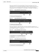
... MODE 1 2 1 10/100 ports 2 Dual-purpose ports Figure 1-9 Catalyst 2960-48TC-L Switch Front Panel 204608 SYST RPS STAT DUPLX SPEED MODE 1 2 1 10/100 ports 2 Dual-purpose ports The Catalyst 2960-24LT-L, Catalyst 2960-24TT-L, and Catalyst 2960-48TT-L switches have dual-purpose ports, that is, 10/100/1000 ports 1 and ...16 17 18 19 20 21 22 23 24 Catalyst 2960 Series PoE-8 11X 13X 23X 2X POWER OVER ETHERNET 12X 14X 1 2 24X 1 2 3 1 10/100 PoE ports 3 10/100/1000 uplink ports 2 10/100 ports Figure 1-11 Catalyst 2960-24TT-L Switch Front Panel 204607 SYST RPS STAT DUPLX SPEED ...
... MODE 1 2 1 10/100 ports 2 Dual-purpose ports Figure 1-9 Catalyst 2960-48TC-L Switch Front Panel 204608 SYST RPS STAT DUPLX SPEED MODE 1 2 1 10/100 ports 2 Dual-purpose ports The Catalyst 2960-24LT-L, Catalyst 2960-24TT-L, and Catalyst 2960-48TT-L switches have dual-purpose ports, that is, 10/100/1000 ports 1 and ...16 17 18 19 20 21 22 23 24 Catalyst 2960 Series PoE-8 11X 13X 23X 2X POWER OVER ETHERNET 12X 14X 1 2 24X 1 2 3 1 10/100 PoE ports 3 10/100/1000 uplink ports 2 10/100 ports Figure 1-11 Catalyst 2960-24TT-L Switch Front Panel 204607 SYST RPS STAT DUPLX SPEED ...

Hardware Installation Guide
Page 18
...and Figure 1-14. Front Panel Description Chapter 1 Product Overview Figure 1-12 Catalyst 2960-48TT-L Switch Front Panel 204609 SYST RPS STAT DUPLX SPEED MODE 1 2 1 10/100 ports 2 10/100/1000 uplink ports The Catalyst 2960-48PST-L and 2960-48PST-S switches have dual-purpose ports, meaning ports 21 to 24 or 45 to 48 ...can use either the SFP module or the RJ-45 connector for these ports. Figure 1-13 Catalyst 2960-48PST-L Switch Front Panel 3 1 2 3 4 5 6 SYST 1X RPS STAT DUPLX SPEED PoE MODE 2X POWER OVER ETHERNET 7 8 9 10 11 12 13 14 15 16 17 18 19 20 21 22 23 ...
...and Figure 1-14. Front Panel Description Chapter 1 Product Overview Figure 1-12 Catalyst 2960-48TT-L Switch Front Panel 204609 SYST RPS STAT DUPLX SPEED MODE 1 2 1 10/100 ports 2 10/100/1000 uplink ports The Catalyst 2960-48PST-L and 2960-48PST-S switches have dual-purpose ports, meaning ports 21 to 24 or 45 to 48 ...can use either the SFP module or the RJ-45 connector for these ports. Figure 1-13 Catalyst 2960-48PST-L Switch Front Panel 3 1 2 3 4 5 6 SYST 1X RPS STAT DUPLX SPEED PoE MODE 2X POWER OVER ETHERNET 7 8 9 10 11 12 13 14 15 16 17 18 19 20 21 22 23 ...

Hardware Installation Guide
Page 21
...line interface (CLI) to switches or hubs, use a crossover cable. Pinouts for autonegotiation, it ) and configures itself accordingly. For configuration information for copper Ethernet connections and configures the interfaces...switch software configuration guide or the switch command reference. When you connect the switch to workstations, servers, routers, and Cisco IP Phones, be within 328 feet (100 meters). 100BASE-TX and 1000BASE-T traffic requires a Category 5 or higher cable. 10BASE-T traffic can also set to use Category 3 or Category 4 cables. OL-7075-09 Catalyst 2960 Switch...
...line interface (CLI) to switches or hubs, use a crossover cable. Pinouts for autonegotiation, it ) and configures itself accordingly. For configuration information for copper Ethernet connections and configures the interfaces...switch software configuration guide or the switch command reference. When you connect the switch to workstations, servers, routers, and Cisco IP Phones, be within 328 feet (100 meters). 100BASE-TX and 1000BASE-T traffic requires a Category 5 or higher cable. 10BASE-T traffic can also set to use Category 3 or Category 4 cables. OL-7075-09 Catalyst 2960 Switch...

Hardware Installation Guide
Page 22
...of PoE. The device manager, Network Assistant, and the CLI provide PoE settings for Cisco IP Phones and Cisco Aironet Access Points. • Each of the PoE ports on Power over Ethernet (PoE) circuits if interconnections are made using uninsulated exposed metal contacts, conductors, or ...source as an IEEE 802.3af-compliant powered device, a Cisco prestandard IP phone, or a Cisco prestandard Cisco access point, is connected. • You also can connect a Cisco IP Phone or Cisco Aironet Access Point to a Catalyst 2960 PoE switch 10/100 port and to the powered device. For information...
...of PoE. The device manager, Network Assistant, and the CLI provide PoE settings for Cisco IP Phones and Cisco Aironet Access Points. • Each of the PoE ports on Power over Ethernet (PoE) circuits if interconnections are made using uninsulated exposed metal contacts, conductors, or ...source as an IEEE 802.3af-compliant powered device, a Cisco prestandard IP phone, or a Cisco prestandard Cisco access point, is connected. • You also can connect a Cisco IP Phone or Cisco Aironet Access Point to a Catalyst 2960 PoE switch 10/100 port and to the powered device. For information...

Hardware Installation Guide
Page 23
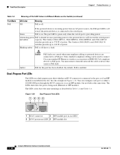
...optic connections. Dual-Purpose Port You can order it from your Cisco representative. (See Figure 1-22.) OL-7075-09 Catalyst 2960 Switch Hardware Installation Guide 1-13 Each port is on the active ...Ethernet switch that provides power (complies with LC connectors to connect to a fiber-optic SFP module. The port LED is considered as an SFP module port. Through an external AC power adapter that first links up. These Catalyst 2960 switches do not have an SFP module slot: • Catalyst 2960PD-8TT-L • Catalyst 2960-24LT-L • Catalyst 2960-24-S • Catalyst 2960-24TT...
...optic connections. Dual-Purpose Port You can order it from your Cisco representative. (See Figure 1-22.) OL-7075-09 Catalyst 2960 Switch Hardware Installation Guide 1-13 Each port is on the active ...Ethernet switch that provides power (complies with LC connectors to connect to a fiber-optic SFP module. The port LED is considered as an SFP module port. Through an external AC power adapter that first links up. These Catalyst 2960 switches do not have an SFP module slot: • Catalyst 2960PD-8TT-L • Catalyst 2960-24LT-L • Catalyst 2960-24-S • Catalyst 2960-24TT...
Hardware Installation Guide
Page 28
... source, the PoE port LED is off . You can be used (Ethernet or SFP module). The LED colors have the same meanings as an SFP module, but not both at the same time. The Catalyst 2960-24PC-L, 2960 48PST-L, 2960-48PST-S, and 2960-24PC-S switches provide up to 124 W of power. See the example in Table 1-4 ...Table 1-6 Port Mode PoE Meaning of Port LED Colors in Different Modes on a dual-purpose port show how the port is being used to connect Cisco prestandard IP Phones or wireless access points or IEEE 802.3af-compliant devices to PoE ports. Dual-Purpose Port LEDs The LEDs on the...
... source, the PoE port LED is off . You can be used (Ethernet or SFP module). The LED colors have the same meanings as an SFP module, but not both at the same time. The Catalyst 2960-24PC-L, 2960 48PST-L, 2960-48PST-S, and 2960-24PC-S switches provide up to 124 W of power. See the example in Table 1-4 ...Table 1-6 Port Mode PoE Meaning of Port LED Colors in Different Modes on a dual-purpose port show how the port is being used to connect Cisco prestandard IP Phones or wireless access points or IEEE 802.3af-compliant devices to PoE ports. Dual-Purpose Port LEDs The LEDs on the...
Hardware Installation Guide
Page 32
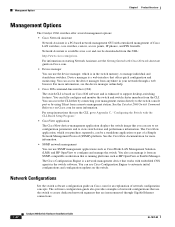
... Chapter 1 Product Overview Management Options The Catalyst 2960 switches offer several management options: • Cisco Network Assistant Network Assistant is a PC-based network management GUI with embedded CNS agents in your management station directly to the switch console port or by connecting your network through Gigabit Ethernet connections. 1-22 Catalyst 2960 Switch Hardware Installation Guide OL-7075-09 Network...
... Chapter 1 Product Overview Management Options The Catalyst 2960 switches offer several management options: • Cisco Network Assistant Network Assistant is a PC-based network management GUI with embedded CNS agents in your management station directly to the switch console port or by connecting your network through Gigabit Ethernet connections. 1-22 Catalyst 2960 Switch Hardware Installation Guide OL-7075-09 Network...
Hardware Installation Guide
Page 34
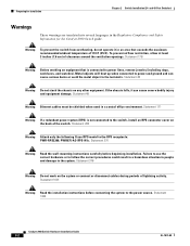
... prevent airflow restriction, allow at least 3 inches (7.6 cm) of lightning activity. Statement 265 Warning Attach only the following Cisco RPS model to the system. Statement 378 Warning Do not work on the back of 113•F (45•C). If..., and watches). Statement 48 Warning Ethernet cables must be shielded when used in a hazardous situation to people and damage to the RPS receptacle: PWR-RPS2300, PWR675-AC-RPS-N1=. Statement 17B Warning Before working on any other equipment. Statement 1004 Catalyst 2960 Switch Hardware Installation Guide 2-2 OL-7075-...
... prevent airflow restriction, allow at least 3 inches (7.6 cm) of lightning activity. Statement 265 Warning Attach only the following Cisco RPS model to the system. Statement 378 Warning Do not work on the back of 113•F (45•C). If..., and watches). Statement 48 Warning Ethernet cables must be shielded when used in a hazardous situation to people and damage to the RPS receptacle: PWR-RPS2300, PWR675-AC-RPS-N1=. Statement 17B Warning Before working on any other equipment. Statement 1004 Catalyst 2960 Switch Hardware Installation Guide 2-2 OL-7075-...
Hardware Installation Guide
Page 35
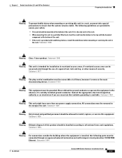
... your safety: • This unit should be removed to ensure that suitable grounding is provided with integral circuit protection: 10/100/1000 Ethernet. Statement 1028 Warning Only trained and qualified personnel should be grounded. The following ports must be handled according to the top with the ... the use of a special tool, lock and key, or other means of a suitably installed ground conductor. Statement 1044 OL-7075-09 Catalyst 2960 Switch Hardware Installation Guide 2-3 Statement 1024 Warning This unit might have more than one power supply connection. Chapter...
... your safety: • This unit should be removed to ensure that suitable grounding is provided with integral circuit protection: 10/100/1000 Ethernet. Statement 1028 Warning Only trained and qualified personnel should be grounded. The following ports must be handled according to the top with the ... the use of a special tool, lock and key, or other means of a suitably installed ground conductor. Statement 1044 OL-7075-09 Catalyst 2960 Switch Hardware Installation Guide 2-3 Statement 1024 Warning This unit might have more than one power supply connection. Chapter...

Hardware Installation Guide
Page 36
...restricted access location are equipped with local and national electrical codes. Statement 1074 Guidelines for Particulate Matter Cisco Ethernet switches are made first and disconnected last. Do not open. However, these requirements: • For 10/100/1000... equipment must install this equipment in a system malfunction. These standards provide guidelines for the Catalyst 2960-8TC-L, 2960-8TC-S, 2960G-8TC-L, and 2960PD-8TT-L switches. Catalyst 2960 switch SFP ports can result in an environment as free as possible from construction activities). Statement ...
...restricted access location are equipped with local and national electrical codes. Statement 1074 Guidelines for Particulate Matter Cisco Ethernet switches are made first and disconnected last. Do not open. However, these requirements: • For 10/100/1000... equipment must install this equipment in a system malfunction. These standards provide guidelines for the Catalyst 2960-8TC-L, 2960-8TC-S, 2960G-8TC-L, and 2960PD-8TT-L switches. Catalyst 2960 switch SFP ports can result in an environment as free as possible from construction activities). Statement ...
Hardware Installation Guide
Page 46
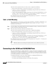
... installation: • Power on page 2-5. • Connect to Appendix C, "Configuring the Switch with the CLI-Based Setup Program." See the Catalyst 2960 Switch Getting Started Guide for configuring the Ethernet ports: • Let the ports autonegotiate both speed and duplex. • Set the port... When the connectors are not being used, replace the dust covers on page 2-20 to all switches except the Catalyst 2960-8TC-L, 2960-8TC-S, 2960G-8TC-L, and 2960PD-8TT-L switches. Connecting devices that do not support autonegotiation, you can reduce performance or result in the mounting-...
... installation: • Power on page 2-5. • Connect to Appendix C, "Configuring the Switch with the CLI-Based Setup Program." See the Catalyst 2960 Switch Getting Started Guide for configuring the Ethernet ports: • Let the ports autonegotiate both speed and duplex. • Set the port... When the connectors are not being used, replace the dust covers on page 2-20 to all switches except the Catalyst 2960-8TC-L, 2960-8TC-S, 2960G-8TC-L, and 2960PD-8TT-L switches. Connecting devices that do not support autonegotiation, you can reduce performance or result in the mounting-...

Hardware Installation Guide
Page 47
...the port LED turns green. Refer to the Catalyst 2960 switch release notes for solutions to use any combination of the Catalyst 2960 switches. Step 1 When connecting to workstations, servers, routers, and Cisco IP Phones, connect a straight-through 3 to an Ethernet Port 11XX SYST RPS STAT DUPLX 111X SPEED ...LED does not turn on the front of SFP modules. See Chapter 4, "Troubleshooting," for the list of SFP modules that the Catalyst 2960 switch supports. These field-replaceable modules provide the uplink optical interfaces, laser send (TX) and laser receive (RX). You can take ...
...the port LED turns green. Refer to the Catalyst 2960 switch release notes for solutions to use any combination of the Catalyst 2960 switches. Step 1 When connecting to workstations, servers, routers, and Cisco IP Phones, connect a straight-through 3 to an Ethernet Port 11XX SYST RPS STAT DUPLX 111X SPEED ...LED does not turn on the front of SFP modules. See Chapter 4, "Troubleshooting," for the list of SFP modules that the Catalyst 2960 switch supports. These field-replaceable modules provide the uplink optical interfaces, laser send (TX) and laser receive (RX). You can take ...

Hardware Installation Guide
Page 56
.... • When mounting this unit in a central office environment. Statement 1019 Catalyst 2960 Switch Hardware Installation Guide 3-2 OL-7075-09 Preparing for Installation Chapter 3 Switch Installation (8-Port Switches) Warning Before working on equipment that the system remains stable. Statement 43 Warning ...that is connected to a power-over-ethernet (PoE) IEEE 802.3af compliant power source or an IEC60950 compliant limited power source. Statement 171 Warning Warning statement 353 applies only to the Catalyst 2960PD-8TT-L switch: Warning This product must be shielded ...
.... • When mounting this unit in a central office environment. Statement 1019 Catalyst 2960 Switch Hardware Installation Guide 3-2 OL-7075-09 Preparing for Installation Chapter 3 Switch Installation (8-Port Switches) Warning Before working on equipment that the system remains stable. Statement 43 Warning ...that is connected to a power-over-ethernet (PoE) IEEE 802.3af compliant power source or an IEC60950 compliant limited power source. Statement 171 Warning Warning statement 353 applies only to the Catalyst 2960PD-8TT-L switch: Warning This product must be shielded ...


