Getting Started Guide
Page 4
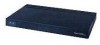
...serial cable (DB-9 -> RJ-45) to console connection Cisco WCS software, web user interface 10/100/1000BASE-T MDI cable Network Distribution system connection LAN link for management software connections WAN or LAN connection to Cisco 2500 Series Wireless Controllers are not currently supported....Points 4 The 2504 controller offers robust coverage with 802.11 a/b/g and delivers unprecedented reliability using 802.11n with Cisco Next-Generation Wireless Solutions and Cisco Enterprise Wireless Mesh. Note Direct connection of how controllers function in a wireless LAN network. To best use ...
...serial cable (DB-9 -> RJ-45) to console connection Cisco WCS software, web user interface 10/100/1000BASE-T MDI cable Network Distribution system connection LAN link for management software connections WAN or LAN connection to Cisco 2500 Series Wireless Controllers are not currently supported....Points 4 The 2504 controller offers robust coverage with 802.11 a/b/g and delivers unprecedented reliability using 802.11n with Cisco Next-Generation Wireless Solutions and Cisco Enterprise Wireless Mesh. Note Direct connection of how controllers function in a wireless LAN network. To best use ...
Getting Started Guide
Page 5
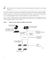
...Figure 2 Front Panel and LEDs 282249 CONSOLE CONSOLE CISCO 2500 Series WIRELESS CONTROLLER RESET Model 2504 1 2 3 4 PWR SYS ALM RESET 1 2 3-4 POE PWR ALM SYS Table 1 Callout WLC2504 Front Panel Component Descriptions Port and LEDs State and Description CONSOLE CPU console port The CPU console port is not available; The boot-...in LED color intensity and hue from unit to 9600. 5 At boot-up the controller configures the RS-232 port as a console port with default settings of the ports and light-emitting diodes (LEDs) for the 2504 controller. Figure 2 shows the front panel...
...Figure 2 Front Panel and LEDs 282249 CONSOLE CONSOLE CISCO 2500 Series WIRELESS CONTROLLER RESET Model 2504 1 2 3 4 PWR SYS ALM RESET 1 2 3-4 POE PWR ALM SYS Table 1 Callout WLC2504 Front Panel Component Descriptions Port and LEDs State and Description CONSOLE CPU console port The CPU console port is not available; The boot-...in LED color intensity and hue from unit to 9600. 5 At boot-up the controller configures the RS-232 port as a console port with default settings of the ports and light-emitting diodes (LEDs) for the 2504 controller. Figure 2 shows the front panel...
Getting Started Guide
Page 7
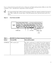
... (PoE) cable to the system The system LED determines if the system is posted on the console screen. • Off-System not receiving power. LED description: • Green-Power is posted on the console screen. LED description: • Blinking Amber-Boot-loader is on • Off-No power ... LED State and Description Pushing the Reset button reboots the system. The power LED light is active and waiting for user input from the system console. • Blinking Green-Boot-loader or booting. • Green-Normal System Operation. • Amber-System failed the bootup process or an error...
... (PoE) cable to the system The system LED determines if the system is posted on the console screen. • Off-System not receiving power. LED description: • Green-Power is posted on the console screen. LED description: • Blinking Amber-Boot-loader is on • Off-No power ... LED State and Description Pushing the Reset button reboots the system. The power LED light is active and waiting for user input from the system console. • Blinking Green-Boot-loader or booting. • Green-Normal System Operation. • Amber-System failed the bootup process or an error...
Getting Started Guide
Page 9
...Contents" section are included in the shipment. Ensure that all packing materials to connect CLI console and controller 9 Required Tools and Information You will need the following items: • One Cisco 2504 Wireless Controller. • One Power supply and power cord (power cord option configurable).... access point cables as required • Command-line interface (CLI) console - Null modem serial cable to the shipping container and save it for damage. If any item is damaged or missing, notify your authorized Cisco sales representative. Check each item for operation: Step 1 Step 2 ...
...Contents" section are included in the shipment. Ensure that all packing materials to connect CLI console and controller 9 Required Tools and Information You will need the following items: • One Cisco 2504 Wireless Controller. • One Power supply and power cord (power cord option configurable).... access point cables as required • Command-line interface (CLI) console - Null modem serial cable to the shipping container and save it for damage. If any item is damaged or missing, notify your authorized Cisco sales representative. Check each item for operation: Step 1 Step 2 ...

Getting Started Guide
Page 11
...outlet. 3 Installing the Controller This section includes the following installation procedures: • Mounting the Controller, page 11 • Connecting the Controller Console Port, page 21 • Securing the Power Adapter Cable, page 21 • Installing a Security Lock, page 23 Mounting the Controller This...11 • RADIUS server IP address, communications port, and secret if you can reach a 100 to the Cisco Wireless LAN Controller Configuration Guide for this installation. Leave at cisco.com. • Status of the 802.11a, 802.11b, 802.11g, or 802.11n networks, either ...
...outlet. 3 Installing the Controller This section includes the following installation procedures: • Mounting the Controller, page 11 • Connecting the Controller Console Port, page 21 • Securing the Power Adapter Cable, page 21 • Installing a Security Lock, page 23 Mounting the Controller This...11 • RADIUS server IP address, communications port, and secret if you can reach a 100 to the Cisco Wireless LAN Controller Configuration Guide for this installation. Leave at cisco.com. • Status of the 802.11a, 802.11b, 802.11g, or 802.11n networks, either ...

Getting Started Guide
Page 13
... Self Test" section on a wall using an optional rack-mount bracket kit that is not included with 19-inch rack mounting brackets and hardware from Cisco. Note Allow 3 inches of the 2504 controller as shown in Figure 5 with #10-32 flat head screws provided in a hazardous situation to people ... before beginning installation. Step 3 Place the switch on a shelf or desk, perform the following tasks to complete the installation: • Connecting the Controller Console Port • Securing the Power Adapter Cable • Connecting to prevent airflow restriction and overheating.
... Self Test" section on a wall using an optional rack-mount bracket kit that is not included with 19-inch rack mounting brackets and hardware from Cisco. Note Allow 3 inches of the 2504 controller as shown in Figure 5 with #10-32 flat head screws provided in a hazardous situation to people ... before beginning installation. Step 3 Place the switch on a shelf or desk, perform the following tasks to complete the installation: • Connecting the Controller Console Port • Securing the Power Adapter Cable • Connecting to prevent airflow restriction and overheating.

Getting Started Guide
Page 15
... 3 Wall mounting screws Step 3 Step 4 After the controller is mounted on the wall, perform the following tasks to complete the installation: • Connecting the Controller Console Port • Securing the Power Adapter Cable • Connecting to the Network For configuration instructions about using the CLI setup program, see the "Running the...
... 3 Wall mounting screws Step 3 Step 4 After the controller is mounted on the wall, perform the following tasks to complete the installation: • Connecting the Controller Console Port • Securing the Power Adapter Cable • Connecting to the Network For configuration instructions about using the CLI setup program, see the "Running the...
Getting Started Guide
Page 17
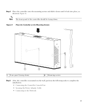
Figure 8 Place the Controller on the Mounting Screws 282085 2 1 2 1 Front panel (facing down until it down ) 2 Mounting screws Step 5 After the controller is mounted ion the wall, perform the following tasks to complete the installation: • Connecting the Controller Console Port • Securing the Power Adapter Cable • Connecting to the Network 17 Step 4 Place the controller onto the mounting screws and slide it lock into place, as shown in Figure 8. Note The front panel of the controller should be facing down.
Figure 8 Place the Controller on the Mounting Screws 282085 2 1 2 1 Front panel (facing down until it down ) 2 Mounting screws Step 5 After the controller is mounted ion the wall, perform the following tasks to complete the installation: • Connecting the Controller Console Port • Securing the Power Adapter Cable • Connecting to the Network 17 Step 4 Place the controller onto the mounting screws and slide it lock into place, as shown in Figure 8. Note The front panel of the controller should be facing down.

Getting Started Guide
Page 20
Figure 10 Mounting the Controller in a 19-Inch Rack 1 282086 1 #10-32 pan-head screws or #12-24 slotted head screws Step 3 Step 4 After the controller is mounted in the rack, perform the following tasks to complete the installation: • Connecting the Controller Console Port • Securing the Power Adapter Cable • Connecting to the Network For configuration instructions about using the CLI setup program, see the "Running the Bootup Script and Power-On Self Test" section on page 23. 20
Figure 10 Mounting the Controller in a 19-Inch Rack 1 282086 1 #10-32 pan-head screws or #12-24 slotted head screws Step 3 Step 4 After the controller is mounted in the rack, perform the following tasks to complete the installation: • Connecting the Controller Console Port • Securing the Power Adapter Cable • Connecting to the Network For configuration instructions about using the CLI setup program, see the "Running the Bootup Script and Power-On Self Test" section on page 23. 20
Getting Started Guide
Page 21
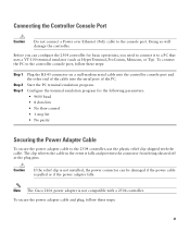
... clip relieves the cable in the event it to the 2504 controller, use the plastic relief clip shipped with a 2504 controller. Note The Cisco 2106 power adapter is not compatible with the cable. Start the PC terminal emulation program. Caution If the relief clip is pulled or if ...secure the power adapter cable to a PC that uses a VT-100 terminal emulator (such as HyperTerminal, ProComm, Minicom, or Tip). Connecting the Controller Console Port Caution Do not connect a Power over Ethernet (PoE) cable to connect it falls and prevents the connector from being sheared off at the plug...
... clip relieves the cable in the event it to the 2504 controller, use the plastic relief clip shipped with a 2504 controller. Note The Cisco 2106 power adapter is not compatible with the cable. Start the PC terminal emulation program. Caution If the relief clip is pulled or if ...secure the power adapter cable to a PC that uses a VT-100 terminal emulator (such as HyperTerminal, ProComm, Minicom, or Tip). Connecting the Controller Console Port Caution Do not connect a Power over Ethernet (PoE) cable to connect it falls and prevents the connector from being sheared off at the plug...
Getting Started Guide
Page 23
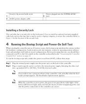
... 3 port. You can install an optional customer-supplied cable lock, such as described in the "Connecting the Controller Console Port" section on the controller as the type that the power connections to the CLI console on page 21. Refer to Figure 3 for the location of the security lock. 4 Running the Bootup Script...
... 3 port. You can install an optional customer-supplied cable lock, such as described in the "Connecting the Controller Console Port" section on the controller as the type that the power connections to the CLI console on page 21. Refer to Figure 3 for the location of the security lock. 4 Running the Bootup Script...
Getting Started Guide
Page 25
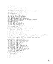
...Cisco AireOS Version 7.0.114.76 Firmware Version PIC 14.0 Initializing OS Services: ok Initializing Serial Services: ok Initializing Network Services: ok Initializing Licensing Services: ok Starting ARP Services: ok Starting Trap Manager: ok Starting Network Interface Management Services: ok Starting System Services: ok Starting Fastpath Hardware Acceleration: ok Starting Fastpath Console... octeon_device_init: found 1 DPs /dev/fpga: No such device or address readCPUConfigData: cardid 0x6060001 Cisco is a trademark of cores(2) Fastpath CPU00: Init MBUF size: 1856, Subsequent MBUF size:...
...Cisco AireOS Version 7.0.114.76 Firmware Version PIC 14.0 Initializing OS Services: ok Initializing Serial Services: ok Initializing Network Services: ok Initializing Licensing Services: ok Starting ARP Services: ok Starting Trap Manager: ok Starting Network Interface Management Services: ok Starting System Services: ok Starting Fastpath Hardware Acceleration: ok Starting Fastpath Console... octeon_device_init: found 1 DPs /dev/fpga: No such device or address readCPUConfigData: cardid 0x6060001 Cisco is a trademark of cores(2) Fastpath CPU00: Init MBUF size: 1856, Subsequent MBUF size:...
Getting Started Guide
Page 27
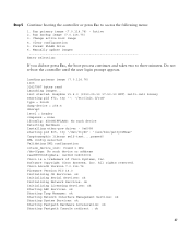
...ok Starting Trap Manager: ok Starting Network Interface Management Services: ok Starting System Services: ok Starting Fastpath Hardware Acceleration: ok Starting Fastpath Console redirect : ok 27 Installing ether-pow driver - 0x6008 starting pid 672, tty '': '/etc/init.d/rcS' type = block dump-...config selected Validating XML configuration octeon_device_init: found 1 DPs /dev/fpga: No such device or address readCPUConfigData: cardid 0x6060001 Cisco is a trademark of Cisco Systems, Inc. Step 5 Continue booting the controller or press Esc to three minutes. Run backup image (7.0.114.75...
...ok Starting Trap Manager: ok Starting Network Interface Management Services: ok Starting System Services: ok Starting Fastpath Hardware Acceleration: ok Starting Fastpath Console redirect : ok 27 Installing ether-pow driver - 0x6008 starting pid 672, tty '': '/etc/init.d/rcS' type = block dump-...config selected Validating XML configuration octeon_device_init: found 1 DPs /dev/fpga: No such device or address readCPUConfigData: cardid 0x6060001 Cisco is a trademark of Cisco Systems, Inc. Step 5 Continue booting the controller or press Esc to three minutes. Run backup image (7.0.114.75...
Getting Started Guide
Page 34
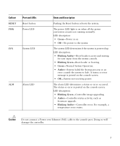
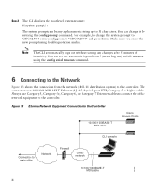
... up to change it by entering the config prompt command. Figure 13 External Network Equipment Connection to the Controller 10/100/1000BASE-T MDI cable Cisco Access Points CLI console Connection to the controller. The connection uses 10/100/1000BASE-T Ethernet (RJ-45 physical port, UTP, Category-5 or higher cable). For example, to...
... up to change it by entering the config prompt command. Figure 13 External Network Equipment Connection to the Controller 10/100/1000BASE-T MDI cable Cisco Access Points CLI console Connection to the controller. The connection uses 10/100/1000BASE-T Ethernet (RJ-45 physical port, UTP, Category-5 or higher cable). For example, to...
Getting Started Guide
Page 36
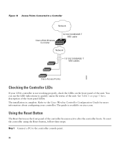
...on page 5 for more information about configuring your controller. Refer to the controller console point. 36 To reset the controller using the Reset button, follow these steps: Step 1 Connect a PC to the Cisco Wireless Controller Configuration Guide for a description of the front panel LEDs. The guide... status of the unit. You can use the LED indications to a Controller Network Cisco 2504 Wireless Controller 10/100/1000BASE-T MDI cable Network 10/100/1000BASE-T MDI cables 282081 Cisco Access Points Checking the Controller LEDs If your 2504 controller is complete. Using the ...
...on page 5 for more information about configuring your controller. Refer to the controller console point. 36 To reset the controller using the Reset button, follow these steps: Step 1 Connect a PC to the Cisco Wireless Controller Configuration Guide for a description of the front panel LEDs. The guide... status of the unit. You can use the LED indications to a Controller Network Cisco 2504 Wireless Controller 10/100/1000BASE-T MDI cable Network 10/100/1000BASE-T MDI cables 282081 Cisco Access Points Checking the Controller LEDs If your 2504 controller is complete. Using the ...
