Service Manual
Page 4
...bulletins and be communicated in the field. The descriptions in this Service Manual are expected to the timing of this Service Manual: 1. CANON PC800s/900s REV.0 AUG. 1999 PRINTED IN JAPAN (IMPRIME AU JAPON) The following rules apply throughout this Service Manual and all cases,... the internal mechanisms of the DC controller PCB to identify and isolate faults in supplying the machine with reference to have a good understanding of the contents of operation. Each chapter contains sections explaining the purpose of specific...
...bulletins and be communicated in the field. The descriptions in this Service Manual are expected to the timing of this Service Manual: 1. CANON PC800s/900s REV.0 AUG. 1999 PRINTED IN JAPAN (IMPRIME AU JAPON) The following rules apply throughout this Service Manual and all cases,... the internal mechanisms of the DC controller PCB to identify and isolate faults in supplying the machine with reference to have a good understanding of the contents of operation. Each chapter contains sections explaining the purpose of specific...
Service Manual
Page 9
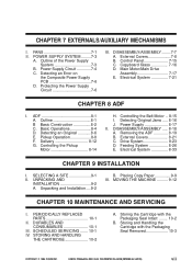
...III. Storing and Handling the Cartridge with the Packaging Seal Intact ........ 10-2 B. CANON PC800s/900s REV.0 AUG. 1999 PRINTED IN JAPAN (IMPRIME AU JAPON) vii Power Supply Circuit 7-4 C. Electrical System 7-21 CHAPTER 8 ADF I . SCHEDULED SERVICING ....... ...IV. Storing the Cartridge with the Packaging Seal Removed 10-3 COPYRIGHT © 1999 CANON INC. Outline 8-1 B Basic Construction 8-2 C. Detecting an Original 8-6 E. Controlling the Pickup Motor 8-14 H. Power Supply 8-17 II. Electrical System 8-33 CHAPTER 9 INSTALLATION I . DURABLES AND CONSUMABLES...
...III. Storing and Handling the Cartridge with the Packaging Seal Intact ........ 10-2 B. CANON PC800s/900s REV.0 AUG. 1999 PRINTED IN JAPAN (IMPRIME AU JAPON) vii Power Supply Circuit 7-4 C. Electrical System 7-21 CHAPTER 8 ADF I . SCHEDULED SERVICING ....... ...IV. Storing the Cartridge with the Packaging Seal Removed 10-3 COPYRIGHT © 1999 CANON INC. Outline 8-1 B Basic Construction 8-2 C. Detecting an Original 8-6 E. Controlling the Pickup Motor 8-14 H. Power Supply 8-17 II. Electrical System 8-33 CHAPTER 9 INSTALLATION I . DURABLES AND CONSUMABLES...
Service Manual
Page 10
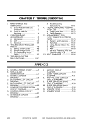
... A-27 H. NOISE FILTER CIRCUIT DIAGRAM A-31 K. HIGH VOLTAGE CONTACT CIRCUIT DIAGRAM A-32 L. SOLVENTS/OILS A-36 viii COPYRIGHT © 1999 CANON INC. Points to Note for Servicing 11-4 II. ADF 11-83 F. COMPOSITE POWER SUPPLY CIRCUIT DIAGRAM A-19 G. AE SENSOR CIRCUIT DIAGRAM A-29 I . SELF DIAGNOSIS 11-86 APPENDIX A. BLANK EXPOSURE (front) CIRCUIT DIAGRAM...
... A-27 H. NOISE FILTER CIRCUIT DIAGRAM A-31 K. HIGH VOLTAGE CONTACT CIRCUIT DIAGRAM A-32 L. SOLVENTS/OILS A-36 viii COPYRIGHT © 1999 CANON INC. Points to Note for Servicing 11-4 II. ADF 11-83 F. COMPOSITE POWER SUPPLY CIRCUIT DIAGRAM A-19 G. AE SENSOR CIRCUIT DIAGRAM A-29 I . SELF DIAGNOSIS 11-86 APPENDIX A. BLANK EXPOSURE (front) CIRCUIT DIAGRAM...
Service Manual
Page 38
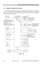
CANON PC800s/900s REV.0 AUG. 1999 PRINTED IN JAPAN (IMPRIME AU JAPON) CHAPTER 2 BASIC OPERATION B. Outline of ... Pre-registration roller paper detection • Delivery paper detection • Vertical path roller paper detection • Single-feeder paper detection Composite power supply PCB Scanning lamp Q900 CPU Fixing heater Highvoltage circuit block Contact PCB • Primary charging roller • Developing cylinder • Transfer charging.../ lens drive motor Scanner cooling fan Sensor/ switch ADF ADF load Figure 2-102 2-2 COPYRIGHT © 1999 CANON INC.
CANON PC800s/900s REV.0 AUG. 1999 PRINTED IN JAPAN (IMPRIME AU JAPON) CHAPTER 2 BASIC OPERATION B. Outline of ... Pre-registration roller paper detection • Delivery paper detection • Vertical path roller paper detection • Single-feeder paper detection Composite power supply PCB Scanning lamp Q900 CPU Fixing heater Highvoltage circuit block Contact PCB • Primary charging roller • Developing cylinder • Transfer charging.../ lens drive motor Scanner cooling fan Sensor/ switch ADF ADF load Figure 2-102 2-2 COPYRIGHT © 1999 CANON INC.
Service Manual
Page 41
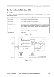
Drive signal Signal (MMD) from the composite power supply. CHAPTER 2 BASIC OPERATION D. Executes constant speed rotation control. CANON PC800s/900s REV.0 AUG. 1999 PRINTED IN JAPAN (IMPRIME AU JAPON) 2-5 Table 2-102 DC controller PCB J103 J203 -6 -3 J104 J204 -1 -7 ...control drive circuit Drive current Clock pulse generator Main motor (M1) Hall IC output MMCLK Composite power supply PCB Reference signal Main motor drive PCB Figure 2-104 COPYRIGHT © 1999 CANON INC. Outline Table 2-102 shows the functions of the main motor control circuit, and Figure 2-...
Drive signal Signal (MMD) from the composite power supply. CHAPTER 2 BASIC OPERATION D. Executes constant speed rotation control. CANON PC800s/900s REV.0 AUG. 1999 PRINTED IN JAPAN (IMPRIME AU JAPON) 2-5 Table 2-102 DC controller PCB J103 J203 -6 -3 J104 J204 -1 -7 ...control drive circuit Drive current Clock pulse generator Main motor (M1) Hall IC output MMCLK Composite power supply PCB Reference signal Main motor drive PCB Figure 2-104 COPYRIGHT © 1999 CANON INC. Outline Table 2-102 shows the functions of the main motor control circuit, and Figure 2-...
Service Manual
Page 45
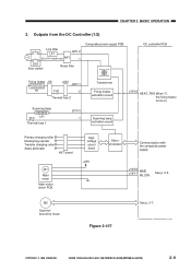
...PCB Highvoltage circuit block +24V Microprocessor Communication with the composite power supply J103-6 MMD J104-1 MLOCK See p. 2-5. CANON PC800s/900s REV.0 AUG. 1999 PRINTED IN JAPAN (IMPRIME AU JAPON) 2-9 COPYRIGHT © 1999 CANON INC. Outputs from the DC Controller (1/2) Line filter LF1 J201-2... (220/240V model only) NF1 -1 DS1 Door switch Noise filter Composite power supply PCB DC controller PCB Fixing heater J16 J434 J207-1 H1 FU2...
...PCB Highvoltage circuit block +24V Microprocessor Communication with the composite power supply J103-6 MMD J104-1 MLOCK See p. 2-5. CANON PC800s/900s REV.0 AUG. 1999 PRINTED IN JAPAN (IMPRIME AU JAPON) 2-9 COPYRIGHT © 1999 CANON INC. Outputs from the DC Controller (1/2) Line filter LF1 J201-2... (220/240V model only) NF1 -1 DS1 Door switch Noise filter Composite power supply PCB DC controller PCB Fixing heater J16 J434 J207-1 H1 FU2...

Service Manual
Page 47
Figure 2-109 COPYRIGHT © 1999 CANON INC. CANON PC800s/900s REV.0 AUG. 1999 PRINTED IN JAPAN (IMPRIME AU JAPON) 2-11 Inputs to and Outputs from the ADF J60 -8 -7 -6 -5 To the ADF -4 -3 -2 -1 To the ADF J24 -4 -3 -2 -1 +24V +5V +5V +24V J202-1 -2 -3 -4 -5 -6 Composite power supply PCB J114-1 REQ -2 -3 ACK -4 -5 TXD -6 -7 RXD -8 J105-6 -5 -4 -3 -2 -1 DC controller PCB See Chapter 8. CHAPTER 2 BASIC OPERATION 5.
Figure 2-109 COPYRIGHT © 1999 CANON INC. CANON PC800s/900s REV.0 AUG. 1999 PRINTED IN JAPAN (IMPRIME AU JAPON) 2-11 Inputs to and Outputs from the ADF J60 -8 -7 -6 -5 To the ADF -4 -3 -2 -1 To the ADF J24 -4 -3 -2 -1 +24V +5V +5V +24V J202-1 -2 -3 -4 -5 -6 Composite power supply PCB J114-1 REQ -2 -3 ACK -4 -5 TXD -6 -7 RXD -8 J105-6 -5 -4 -3 -2 -1 DC controller PCB See Chapter 8. CHAPTER 2 BASIC OPERATION 5.
Service Manual
Page 59
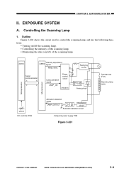
CANON PC800s/900s REV.0 AUG. 1999 PRINTED IN JAPAN (IMPRIME AU JAPON) 3-9 Outline Figure 3-201 shows the circuit used to control the scanning lamp, and has ... fuse (FU1) Scanning lamp (LA1) Microprocessor Microprocessor VR107 DC controller PCB Activation detection signal LAMP_DETECT Rectifying circuit Activation detection circuit Composite power supply PCB Figure 3-201 COPYRIGHT © 1999 CANON INC. EXPOSURE SYSTEM A. CHAPTER 3 EXPOSURE SYSTEM II. tions: • Turning on/off the scanning lamp. • Controlling the intensity of the scanning...
CANON PC800s/900s REV.0 AUG. 1999 PRINTED IN JAPAN (IMPRIME AU JAPON) 3-9 Outline Figure 3-201 shows the circuit used to control the scanning lamp, and has ... fuse (FU1) Scanning lamp (LA1) Microprocessor Microprocessor VR107 DC controller PCB Activation detection signal LAMP_DETECT Rectifying circuit Activation detection circuit Composite power supply PCB Figure 3-201 COPYRIGHT © 1999 CANON INC. EXPOSURE SYSTEM A. CHAPTER 3 EXPOSURE SYSTEM II. tions: • Turning on/off the scanning lamp. • Controlling the intensity of the scanning...
Service Manual
Page 60
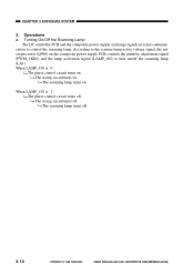
...arcing circuit turns off . 3-10 COPYRIGHT © 1999 CANON INC. The scanning lamp turns off . The scanning lamp turns on . Operations a. Turning On/Off the Scanning Lamp The DC controller PCB and the composite power supply exchange signals in serial communication to turn on . When... LAMP_ON is '0', The phase control circuit turns on /off . CHAPTER 3 EXPOSURE SYSTEM 2. CANON PC800s/900s REV.0 AUG. 1999 PRINTED IN JAPAN (IMPRIME AU ...
...arcing circuit turns off . 3-10 COPYRIGHT © 1999 CANON INC. The scanning lamp turns off . The scanning lamp turns on . Operations a. Turning On/Off the Scanning Lamp The DC controller PCB and the composite power supply exchange signals in serial communication to turn on . When... LAMP_ON is '0', The phase control circuit turns on /off . CHAPTER 3 EXPOSURE SYSTEM 2. CANON PC800s/900s REV.0 AUG. 1999 PRINTED IN JAPAN (IMPRIME AU ...
Service Manual
Page 61
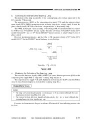
... the scanning lamp. ment signal (PWM_1KHz) in terms of actual voltage by way of VR107 mounted on the composite power supply PCB sends the intensity adjust- CANON PC800s/900s REV.0 AUG. 1999 PRINTED IN JAPAN (IMPRIME AU JAPON) 3-11 The microprocessor (Q900) on the DC controller... PCB between 10% and 90% in serial. COPYRIGHT © 1999 CANON INC. ning lamp activation signal has been sent. • The lamp activation detection signal has been detected for 2 sec. The composite power supply PCB sends the lamp activation signal to the setting of phase control. ...
... the scanning lamp. ment signal (PWM_1KHz) in terms of actual voltage by way of VR107 mounted on the composite power supply PCB sends the intensity adjust- CANON PC800s/900s REV.0 AUG. 1999 PRINTED IN JAPAN (IMPRIME AU JAPON) 3-11 The microprocessor (Q900) on the DC controller... PCB between 10% and 90% in serial. COPYRIGHT © 1999 CANON INC. ning lamp activation signal has been sent. • The lamp activation detection signal has been detected for 2 sec. The composite power supply PCB sends the lamp activation signal to the setting of phase control. ...
Service Manual
Page 96
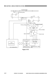
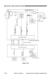
CANON PC800s/900s REV.0 AUG. 1999 PRINTED IN JAPAN (IMPRIME AU JAPON) CHAPTER 4 IMAGE FORMATION SYSTEM Copyboard glass Scanning lamp AE sensor Side blanking lamp Lens Primary charging roller Developing cylinder Photosensitive drum Drum cartridge Static eliminator Transfer roller Q101 Microprocessor DC controller PCB Lamp regulator block High-voltage circuit block Q900 Microprocessor Composite power supply PCB Figure 4-101 4-2 COPYRIGHT © 1999 CANON INC.
CANON PC800s/900s REV.0 AUG. 1999 PRINTED IN JAPAN (IMPRIME AU JAPON) CHAPTER 4 IMAGE FORMATION SYSTEM Copyboard glass Scanning lamp AE sensor Side blanking lamp Lens Primary charging roller Developing cylinder Photosensitive drum Drum cartridge Static eliminator Transfer roller Q101 Microprocessor DC controller PCB Lamp regulator block High-voltage circuit block Q900 Microprocessor Composite power supply PCB Figure 4-101 4-2 COPYRIGHT © 1999 CANON INC.

Service Manual
Page 99
Main transformer T101 CHAPTER 4 IMAGE FORMATION SYSTEM Voltage separation circuit T508 High-voltage transformer for primary charging Primary charging roller Photosensitive drum Amplifier DC bias control signal PDC_PWM DC voltage monitor signal PDC_S AC component current monitor signal PAC_S AC bias output signal PAC_OUT -5 PR_DC_ON J103 J203 -4 Microprocessor (Q900) Composite power supply PCB Serial communication Microprocessor (Q101) Figure 4-103 DC controller PCB COPYRIGHT © 1999 CANON INC. CANON PC800s/900s REV.0 AUG. 1999 PRINTED IN JAPAN (IMPRIME AU JAPON) 4-5
Main transformer T101 CHAPTER 4 IMAGE FORMATION SYSTEM Voltage separation circuit T508 High-voltage transformer for primary charging Primary charging roller Photosensitive drum Amplifier DC bias control signal PDC_PWM DC voltage monitor signal PDC_S AC component current monitor signal PAC_S AC bias output signal PAC_OUT -5 PR_DC_ON J103 J203 -4 Microprocessor (Q900) Composite power supply PCB Serial communication Microprocessor (Q101) Figure 4-103 DC controller PCB COPYRIGHT © 1999 CANON INC. CANON PC800s/900s REV.0 AUG. 1999 PRINTED IN JAPAN (IMPRIME AU JAPON) 4-5
Service Manual
Page 100
...bias output signal (PAC_OUT), thereby applying an AC bias to the primary charging roller is generated, the microprocessor (Q900) on the composite power supply PCB detects the DC voltage monitor signal (PDC_S) and the AC component current monitor signal (PAC_S), compares their levels against the reference levels,... according to the differences so as to the primary charging roller are sent. CANON PC800s/900s REV.0 AUG. 1999 PRINTED IN JAPAN (IMPRIME AU JAPON) When the Copy Start key is turned on the composite power supply PCB so that they remain a specific level. Turning On and Off the...
...bias output signal (PAC_OUT), thereby applying an AC bias to the primary charging roller is generated, the microprocessor (Q900) on the composite power supply PCB detects the DC voltage monitor signal (PDC_S) and the AC component current monitor signal (PAC_S), compares their levels against the reference levels,... according to the differences so as to the primary charging roller are sent. CANON PC800s/900s REV.0 AUG. 1999 PRINTED IN JAPAN (IMPRIME AU JAPON) When the Copy Start key is turned on the composite power supply PCB so that they remain a specific level. Turning On and Off the...

Service Manual
Page 101
... signal (serial signal) generated by the cleaning bias from the transfer roller. copy image area (-400 V). CANON PC800s/900s REV.0 AUG. 1999 PRINTED IN JAPAN (IMPRIME AU JAPON) 4-7 The microprocessor (Q900) on the composite power supply PCB varies the DC bias control signal (PDC_PWM) to a positive potential otherwise caused by the DC... SCFW SCRV SCFW SCRV LSTR STBY Main motor (M1) Scanning lamp (LA1) Primary DC bias Primary AC bias -400V -625V Figure 4-104 COPYRIGHT © 1999 CANON INC. CHAPTER 4 IMAGE FORMATION SYSTEM d.
... signal (serial signal) generated by the cleaning bias from the transfer roller. copy image area (-400 V). CANON PC800s/900s REV.0 AUG. 1999 PRINTED IN JAPAN (IMPRIME AU JAPON) 4-7 The microprocessor (Q900) on the composite power supply PCB varies the DC bias control signal (PDC_PWM) to a positive potential otherwise caused by the DC... SCFW SCRV SCFW SCRV LSTR STBY Main motor (M1) Scanning lamp (LA1) Primary DC bias Primary AC bias -400V -625V Figure 4-104 COPYRIGHT © 1999 CANON INC. CHAPTER 4 IMAGE FORMATION SYSTEM d.
Service Manual
Page 102
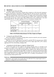
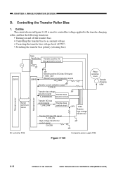
Controlling the Transfer Roller Bias 1. CANON PC800s/900s REV.0 AUG. 1999 PRINTED IN JAPAN (IMPRIME AU JAPON) Outline The circuit shown in Figure 4-105 is used to control the voltage applied ... T_FW_ON High-voltage transformer control signal CLK32K +24V T302 Transfer high-voltage transformer Photosensitive drum Transfer charging roller DC controller PCB Figure 4-105 Composite power supply PCB 4-8 COPYRIGHT © 1999 CANON INC. CHAPTER 4 IMAGE FORMATION SYSTEM D.
Controlling the Transfer Roller Bias 1. CANON PC800s/900s REV.0 AUG. 1999 PRINTED IN JAPAN (IMPRIME AU JAPON) Outline The circuit shown in Figure 4-105 is used to control the voltage applied ... T_FW_ON High-voltage transformer control signal CLK32K +24V T302 Transfer high-voltage transformer Photosensitive drum Transfer charging roller DC controller PCB Figure 4-105 Composite power supply PCB 4-8 COPYRIGHT © 1999 CANON INC. CHAPTER 4 IMAGE FORMATION SYSTEM D.
Service Manual
Page 103
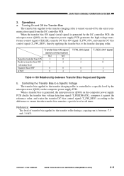
...level of transfer bias applied to the transfer roller during a copying run is generated by the microprocessor (Q900) on the composite power supply PCB generates the high-voltage transformer control signal (CLK32K), transfer DC bias ON signal (T_FW_ON), and transfer DC bias control signal (...T_FW_DRV), thereby applying the transfer bias to the transfer charging roller. CHAPTER 4 IMAGE FORMATION SYSTEM 2. Operations a. CANON PC800s/900s REV.0 AUG. 1999 PRINTED IN JAPAN (IMPRIME AU JAPON) 4-9 Negative transfer bias ON Positive transfer bias ON (cleaning bias) ...
...level of transfer bias applied to the transfer roller during a copying run is generated by the microprocessor (Q900) on the composite power supply PCB generates the high-voltage transformer control signal (CLK32K), transfer DC bias ON signal (T_FW_ON), and transfer DC bias control signal (...T_FW_DRV), thereby applying the transfer bias to the transfer charging roller. CHAPTER 4 IMAGE FORMATION SYSTEM 2. Operations a. CANON PC800s/900s REV.0 AUG. 1999 PRINTED IN JAPAN (IMPRIME AU JAPON) 4-9 Negative transfer bias ON Positive transfer bias ON (cleaning bias) ...
Service Manual
Page 104
... bias (ATVC) Transfer bias 1.2sec (approx.) 0.8sec (approx.) 0.7sec (approx.) 1.6sec(approx.) Figure 4-106 4-10 COPYRIGHT © 1999 CANON INC. Reference: While the transfer charging roller makes a single rotation, the microprocessor (Q900) checks the transfer current detection signal four times, and determines...bias to correct the changes in the environment. In response to the signal, the microprocessor (Q900) on the composite power supply PCB checks the transfer current detection signal (T_FW_S), and varies the transfer bias applied to the transfer charging roller so that...
... bias (ATVC) Transfer bias 1.2sec (approx.) 0.8sec (approx.) 0.7sec (approx.) 1.6sec(approx.) Figure 4-106 4-10 COPYRIGHT © 1999 CANON INC. Reference: While the transfer charging roller makes a single rotation, the microprocessor (Q900) checks the transfer current detection signal four times, and determines...bias to correct the changes in the environment. In response to the signal, the microprocessor (Q900) on the composite power supply PCB checks the transfer current detection signal (T_FW_S), and varies the transfer bias applied to the transfer charging roller so that...
Service Manual
Page 106
CANON PC800s/900s REV.0 AUG. 1999 PRINTED IN JAPAN (IMPRIME AU JAPON) CHAPTER 4 IMAGE FORMATION SYSTEM Main transformer T101 High-voltage transformer for developing/static eliminator ... Static eliminator DC bias control signal BIAS_PWM DC bias monitor signal BIAS_S AC bias oscillation signal ACBIAS J103 J203 -3 -6 DV_DC_ON DV_AC_ON -7 Microprocessor (Q900) Composite power supply PCB Serial communication Microprocessor (Q101) -2 AE signal Copy density setting signal Copy density correction signal AE sensor PCB Control panel Density correction switch (SW101) DC...
CANON PC800s/900s REV.0 AUG. 1999 PRINTED IN JAPAN (IMPRIME AU JAPON) CHAPTER 4 IMAGE FORMATION SYSTEM Main transformer T101 High-voltage transformer for developing/static eliminator ... Static eliminator DC bias control signal BIAS_PWM DC bias monitor signal BIAS_S AC bias oscillation signal ACBIAS J103 J203 -3 -6 DV_DC_ON DV_AC_ON -7 Microprocessor (Q900) Composite power supply PCB Serial communication Microprocessor (Q101) -2 AE signal Copy density setting signal Copy density correction signal AE sensor PCB Control panel Density correction switch (SW101) DC...

Service Manual
Page 107
...on and off by the DC controller PCB. The microprocessor (Q900) on the composite power supply PCB sends the DC bias control signal (BIAS_PWM), thereby applying a DC bias to the developing cylinder. posite power supply PCB a specific period of time after copy paper has moved past the registration sensor. ... gener- Turning On and Off the AC Bias The AC bias is turned on and off by the signal communica- COPYRIGHT © 1999 CANON INC. CANON PC800s/900s REV.0 AUG. 1999 PRINTED IN JAPAN (IMPRIME AU JAPON) 4-13 The AC bias is applied to the developing cylinder. DC bias...
...on and off by the DC controller PCB. The microprocessor (Q900) on the composite power supply PCB sends the DC bias control signal (BIAS_PWM), thereby applying a DC bias to the developing cylinder. posite power supply PCB a specific period of time after copy paper has moved past the registration sensor. ... gener- Turning On and Off the AC Bias The AC bias is turned on and off by the signal communica- COPYRIGHT © 1999 CANON INC. CANON PC800s/900s REV.0 AUG. 1999 PRINTED IN JAPAN (IMPRIME AU JAPON) 4-13 The AC bias is applied to the developing cylinder. DC bias...
Service Manual
Page 108
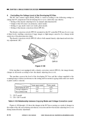
... density correction switch (SW101) mounted on the DC controller PCB may be set to how the density adjusting lever is selected. Developing DC bias Voltage supplied to the scanning lamp Toner save mode -75V -2V*1 -3V*2 Photo mode +15V -2V*1 -3V*2 *1: 120 V model *2: 220 / 240 V model Table 4-105...and how the density adjusting lever is set . The density correction switch (SW101) affects both manual density adjustment and auto density adjustment (AE). CANON PC800s/900s REV.0 AUG. 1999 PRINTED IN JAPAN (IMPRIME AU JAPON) Controlling the Voltage Level of the Developing DC Bias The DC bias control...
... density correction switch (SW101) mounted on the DC controller PCB may be set to how the density adjusting lever is selected. Developing DC bias Voltage supplied to the scanning lamp Toner save mode -75V -2V*1 -3V*2 Photo mode +15V -2V*1 -3V*2 *1: 120 V model *2: 220 / 240 V model Table 4-105...and how the density adjusting lever is set . The density correction switch (SW101) affects both manual density adjustment and auto density adjustment (AE). CANON PC800s/900s REV.0 AUG. 1999 PRINTED IN JAPAN (IMPRIME AU JAPON) Controlling the Voltage Level of the Developing DC Bias The DC bias control...


