
Service Manual
Page 3
...how they may be disassembled/assembled and adjusted. Chapter 9 Installation introduces requirements for the site of periodically replaced parts and consumables/durables and scheduled servicing charts. Chapter 11 Troubleshooting provides tables of operation used for the machine's ... used for the machine's exposure system. Appendix contains a general timing chart and general circuit diagrams. COPYRIGHT © 1999 CANON INC. Chapter 4 Image Formation System discusses the principles of maintenance/inspection, standards/ adjustments, and problem identification (image fault/...
...how they may be disassembled/assembled and adjusted. Chapter 9 Installation introduces requirements for the site of periodically replaced parts and consumables/durables and scheduled servicing charts. Chapter 11 Troubleshooting provides tables of operation used for the machine's ... used for the machine's exposure system. Appendix contains a general timing chart and general circuit diagrams. COPYRIGHT © 1999 CANON INC. Chapter 4 Image Formation System discusses the principles of maintenance/inspection, standards/ adjustments, and problem identification (image fault/...
Service Manual
Page 7
... 3 EXPOSURE SYSTEM I . Outline 3-1 B. Lens Drive System 3-3 D. Basic Sequence of Electrical Circuitry 2-2 C. Controlling the Scanning Lamp 3-9 III. Exposure System 3-37 COPYRIGHT © 1999 CANON INC. OPERATIONS 3-1 A. ADF 1-8 III. NAMES OF PARTS 1-10 A. IMAGE FORMATION 1-20 A. Outline 1-20 CHAPTER 2 BASIC OPERATION I . EXPOSURE SYSTEM 3-9 A. SPECIFICATIONS 1-2 A. DISASSEMBLY/ASSEMBLY ..... 3-12 A. Scanner Drive Assembly .... 3-13 B. Varying the Reproduction...
... 3 EXPOSURE SYSTEM I . Outline 3-1 B. Lens Drive System 3-3 D. Basic Sequence of Electrical Circuitry 2-2 C. Controlling the Scanning Lamp 3-9 III. Exposure System 3-37 COPYRIGHT © 1999 CANON INC. OPERATIONS 3-1 A. ADF 1-8 III. NAMES OF PARTS 1-10 A. IMAGE FORMATION 1-20 A. Outline 1-20 CHAPTER 2 BASIC OPERATION I . EXPOSURE SYSTEM 3-9 A. SPECIFICATIONS 1-2 A. DISASSEMBLY/ASSEMBLY ..... 3-12 A. Scanner Drive Assembly .... 3-13 B. Varying the Reproduction...
Service Manual
Page 9
... Motor 8-14 H. DISASSEMBLY/ASSEMBLY ..... 8-18 A. Unpacking and Installation ....9-2 B. PERIODICALLY REPLACED PARTS 10-1 II. STORING AND HANDLING THE CARTRIDGE 10-2 A. CANON PC800s/900s REV.0 AUG. 1999 PRINTED IN JAPAN (IMPRIME AU JAPON) vii Control Panel ... Delivery 8-12 G. Main Motor/Main Drive Assembly 7-17 E. Storing the Cartridge with the Packaging Seal Removed 10-3 COPYRIGHT © 1999 CANON INC. Detecting an Original 8-6 E. Power Supply Circuit 7-4 C. CHAPTER 7 EXTERNALS/AUXILIARY MECHANISMS I . FANS 7-1 II. DISASSEMBLY/ASSEMBLY ........7-7...
... Motor 8-14 H. DISASSEMBLY/ASSEMBLY ..... 8-18 A. Unpacking and Installation ....9-2 B. PERIODICALLY REPLACED PARTS 10-1 II. STORING AND HANDLING THE CARTRIDGE 10-2 A. CANON PC800s/900s REV.0 AUG. 1999 PRINTED IN JAPAN (IMPRIME AU JAPON) vii Control Panel ... Delivery 8-12 G. Main Motor/Main Drive Assembly 7-17 E. Storing the Cartridge with the Packaging Seal Removed 10-3 COPYRIGHT © 1999 CANON INC. Detecting an Original 8-6 E. Power Supply Circuit 7-4 C. CHAPTER 7 EXTERNALS/AUXILIARY MECHANISMS I . FANS 7-1 II. DISASSEMBLY/ASSEMBLY ........7-7...
Service Manual
Page 10
...POWER SUPPLY CIRCUIT DIAGRAM A-19 G. BLANK EXPOSURE (front) CIRCUIT DIAGRAM A-33 M. SOLVENTS/OILS A-36 viii COPYRIGHT © 1999 CANON INC. Copy Paper Jam 11-75 B. NOISE FILTER CIRCUIT DIAGRAM A-31 K. Electrical 11-41 III. Sample Image Faults ....... ...AU JAPON) MAINTENANCE AND INSPECTION 11-3 A. STANDARDS AND ADJUSTMENTS 11-5 A. TROUBLESHOOTING MALFUNCTIONS 11-61 A. ARRANGEMENT AND FUNCTIONS OF ELECTRICAL PARTS 11-79 A. Switches 11-80 C. GENERAL TIMING CHART ........ CONTROL PANEL CIRCUIT DIAGRAM A-27 H. BLANK EXPOSURE (rear) CIRCUIT ...
...POWER SUPPLY CIRCUIT DIAGRAM A-19 G. BLANK EXPOSURE (front) CIRCUIT DIAGRAM A-33 M. SOLVENTS/OILS A-36 viii COPYRIGHT © 1999 CANON INC. Copy Paper Jam 11-75 B. NOISE FILTER CIRCUIT DIAGRAM A-31 K. Electrical 11-41 III. Sample Image Faults ....... ...AU JAPON) MAINTENANCE AND INSPECTION 11-3 A. STANDARDS AND ADJUSTMENTS 11-5 A. TROUBLESHOOTING MALFUNCTIONS 11-61 A. ARRANGEMENT AND FUNCTIONS OF ELECTRICAL PARTS 11-79 A. Switches 11-80 C. GENERAL TIMING CHART ........ CONTROL PANEL CIRCUIT DIAGRAM A-27 H. BLANK EXPOSURE (rear) CIRCUIT ...
Service Manual
Page 11
SPECIFICATIONS 1-2 A. Copier 1-2 B. ADF 1-8 III. I. ROUTINE MAINTENANCE BY THE USER 1-17 VI. Cross Section 1-13 IV. IMAGE FORMATION 1-20 A. CANON PC800s/900s REV.0 AUG. 1999 PRINTED IN JAPAN (IMPRIME AU JAPON) CHAPTER 1 GENERAL DESCRIPTION This chapter provides specifications of the machine, instructions on how to operate the machine, and an outline of copying process. NAMES OF PARTS 1-10 A. Outline 1-20 COPYRIGHT © 1999 CANON INC. USING THE MACHINE 1-15 A. FEATURES 1-1 II. Control Panel 1-15 V. External View 1-10 B.
SPECIFICATIONS 1-2 A. Copier 1-2 B. ADF 1-8 III. I. ROUTINE MAINTENANCE BY THE USER 1-17 VI. Cross Section 1-13 IV. IMAGE FORMATION 1-20 A. CANON PC800s/900s REV.0 AUG. 1999 PRINTED IN JAPAN (IMPRIME AU JAPON) CHAPTER 1 GENERAL DESCRIPTION This chapter provides specifications of the machine, instructions on how to operate the machine, and an outline of copying process. NAMES OF PARTS 1-10 A. Outline 1-20 COPYRIGHT © 1999 CANON INC. USING THE MACHINE 1-15 A. FEATURES 1-1 II. Control Panel 1-15 V. External View 1-10 B.
Service Manual
Page 22
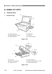
CHAPTER 1 GENERAL DESCRIPTION III. Copyboard Type [2] [6] [3] [5] [4] [1] Copyboard cover [2] Static eliminator cleaner [3] Manual feed tray [4] Right door [5] Cassette [6] Copyboard glass Figure 1-301 [4] [3] [5] [2] [1] [6] [1] Copy tray [2] Power cord connector [3] Open/close lever [4] Static eliminator [5] Copy density correction switch [6] Delivery guide plate Figure 1-302 1-10 COPYRIGHT © 1999 CANON INC. NAMES OF PARTS A. CANON PC800s/900s REV.0 AUG. 1999 PRINTED IN JAPAN (IMPRIME AU JAPON) External View [1] 1.
CHAPTER 1 GENERAL DESCRIPTION III. Copyboard Type [2] [6] [3] [5] [4] [1] Copyboard cover [2] Static eliminator cleaner [3] Manual feed tray [4] Right door [5] Cassette [6] Copyboard glass Figure 1-301 [4] [3] [5] [2] [1] [6] [1] Copy tray [2] Power cord connector [3] Open/close lever [4] Static eliminator [5] Copy density correction switch [6] Delivery guide plate Figure 1-302 1-10 COPYRIGHT © 1999 CANON INC. NAMES OF PARTS A. CANON PC800s/900s REV.0 AUG. 1999 PRINTED IN JAPAN (IMPRIME AU JAPON) External View [1] 1.
Service Manual
Page 35
... Electrical Circuitry 2-2 C. Functional Construction ........2-1 B. Controlling the Main Motor (M1 2-5 E. Outline of each operation, relationships between electrical and mechanical systems, and timing at which each associated part is turned on. Basic Sequence of Operations 2-3 D. Inputs to and Outputs from the DC Controller 2-7 COPYRIGHT © 1999 CANON INC. Process speed 96 mm/sec I.
... Electrical Circuitry 2-2 C. Functional Construction ........2-1 B. Controlling the Main Motor (M1 2-5 E. Outline of each operation, relationships between electrical and mechanical systems, and timing at which each associated part is turned on. Basic Sequence of Operations 2-3 D. Inputs to and Outputs from the DC Controller 2-7 COPYRIGHT © 1999 CANON INC. Process speed 96 mm/sec I.
Service Manual
Page 41
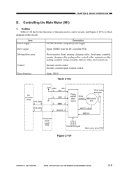
...supply Description 24 VDC from the DC controller PCB. Executes constant speed rotation control. Error detection Issues 'E010'. Moving/drive parts Photosensitive drum, primary charging roller, developing assembly, transfer charging roller, pickup roller, vertical roller, registration roller, feeding assembly..., fixing assembly, delivery roller, heat exhaust fan Control Executes on/off control. CANON PC800s/900s REV.0 AUG. 1999 PRINTED IN JAPAN (IMPRIME AU JAPON) 2-5 CHAPTER 2 BASIC OPERATION D. Outline Table 2-102...
...supply Description 24 VDC from the DC controller PCB. Executes constant speed rotation control. Error detection Issues 'E010'. Moving/drive parts Photosensitive drum, primary charging roller, developing assembly, transfer charging roller, pickup roller, vertical roller, registration roller, feeding assembly..., fixing assembly, delivery roller, heat exhaust fan Control Executes on/off control. CANON PC800s/900s REV.0 AUG. 1999 PRINTED IN JAPAN (IMPRIME AU JAPON) 2-5 CHAPTER 2 BASIC OPERATION D. Outline Table 2-102...

Service Manual
Page 62
... to mount the grounding wire and Varistors come with wider thread intervals). Unless otherwise instructed, assemble the parts by type (length, diameter) and location. 4. As necessary, cut the harness band. 6. A few of its part removed. 7. CANON PC800s/900s REV.0 AUG. 1999 PRINTED IN JAPAN (IMPRIME AU JAPON) Before starting the work, turn off...
... to mount the grounding wire and Varistors come with wider thread intervals). Unless otherwise instructed, assemble the parts by type (length, diameter) and location. 4. As necessary, cut the harness band. 6. A few of its part removed. 7. CANON PC800s/900s REV.0 AUG. 1999 PRINTED IN JAPAN (IMPRIME AU JAPON) Before starting the work, turn off...
Service Manual
Page 104
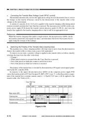
...< Timing > • While initial rotation is executed after the Copy Start key is pressed • Part of the period in which the scanner is moved in reverse • Part of the transfer bias to correct the changes in the transfer efficiency caused by the DC controller PCB.... bias Reference bias (ATVC) Transfer bias 1.2sec (approx.) 0.8sec (approx.) 0.7sec (approx.) 1.6sec(approx.) Figure 4-106 4-10 COPYRIGHT © 1999 CANON INC. To remove excess toner, a positive voltage is applied to the transfer roller as when a jam occurs if left unattended. CHAPTER 4 IMAGE FORMATION SYSTEM...
...< Timing > • While initial rotation is executed after the Copy Start key is pressed • Part of the period in which the scanner is moved in reverse • Part of the transfer bias to correct the changes in the transfer efficiency caused by the DC controller PCB.... bias Reference bias (ATVC) Transfer bias 1.2sec (approx.) 0.8sec (approx.) 0.7sec (approx.) 1.6sec(approx.) Figure 4-106 4-10 COPYRIGHT © 1999 CANON INC. To remove excess toner, a positive voltage is applied to the transfer roller as when a jam occurs if left unattended. CHAPTER 4 IMAGE FORMATION SYSTEM...

Service Manual
Page 116
...wider thread intervals). Identify the screws by reversing the steps used to disassemble it. 3. Unless otherwise instructed, assemble the parts by type (length, diameter) and location. 4. As a rule, do not operate the machine with any screws indiscriminately. 4-22 COPYRIGHT ©...; 1999 CANON INC. As necessary, cut the harnessband. 6. A few of its part removed. 7. CANON PC800s/900s REV.0 AUG. 1999 PRINTED IN JAPAN (IMPRIME AU JAPON) Before starting the work, turn off the...
...wider thread intervals). Identify the screws by reversing the steps used to disassemble it. 3. Unless otherwise instructed, assemble the parts by type (length, diameter) and location. 4. As a rule, do not operate the machine with any screws indiscriminately. 4-22 COPYRIGHT ©...; 1999 CANON INC. As necessary, cut the harnessband. 6. A few of its part removed. 7. CANON PC800s/900s REV.0 AUG. 1999 PRINTED IN JAPAN (IMPRIME AU JAPON) Before starting the work, turn off the...

Service Manual
Page 142
Use the washers where necessary. (The screws used to disassemble it. 3. CANON PC800s/900s REV.0 AUG. 1999 PRINTED IN JAPAN (IMPRIME AU JAPON) CHAPTER 5 PICK-UP/FEEDING SYSTEM II. tors come with wider thread intervals). As necessary, .... 7. DISASSEMBLY/ASSEMBLY As needed, disassemble/assemble the machine with any screws indiscriminately. 5-18 COPYRIGHT © 1999 CANON INC. Unless otherwise instructed, assemble the parts by type (length, diameter) and location. 4. Do not use any of the screws used are special screws (with a washer to mount the grounding wire and ...
Use the washers where necessary. (The screws used to disassemble it. 3. CANON PC800s/900s REV.0 AUG. 1999 PRINTED IN JAPAN (IMPRIME AU JAPON) CHAPTER 5 PICK-UP/FEEDING SYSTEM II. tors come with wider thread intervals). As necessary, .... 7. DISASSEMBLY/ASSEMBLY As needed, disassemble/assemble the machine with any screws indiscriminately. 5-18 COPYRIGHT © 1999 CANON INC. Unless otherwise instructed, assemble the parts by type (length, diameter) and location. 4. Do not use any of the screws used are special screws (with a washer to mount the grounding wire and ...
Service Manual
Page 174
...any of the screws used are special screws (with a washer to ensure electrical continuity.) 5. CANON PC800s/900s REV.0 AUG. 1999 PRINTED IN JAPAN (IMPRIME AU JAPON) Unless otherwise instructed, assemble the parts by type (length, diameter) and location. 4. Use the washers where necessary. (The screws ...used to mount the grounding wire and Varis- Identify the screws by reversing the steps used to disassemble it. 3. A few of its part removed. 7. Before starting the work, turn off the power switch and disconnect the power plug for safety. 2. As necessary, cut the harness band...
...any of the screws used are special screws (with a washer to ensure electrical continuity.) 5. CANON PC800s/900s REV.0 AUG. 1999 PRINTED IN JAPAN (IMPRIME AU JAPON) Unless otherwise instructed, assemble the parts by type (length, diameter) and location. 4. Use the washers where necessary. (The screws ...used to mount the grounding wire and Varis- Identify the screws by reversing the steps used to disassemble it. 3. A few of its part removed. 7. Before starting the work, turn off the power switch and disconnect the power plug for safety. 2. As necessary, cut the harness band...
Service Manual
Page 179
...FANS 7-1 II. POWER SUPPLY SYSTEM .........7-3 A. Outline of operation. Detecting an Error on the Composite Power Supply PCB 7-6 D. CANON PC800s/900s REV.0 AUG. 1999 PRINTED IN JAPAN (IMPRIME AU JAPON) Control Panel 7-15 C. Power Supply Circuit 7-4 C. DISASSEMBLY... Supply Circuit 7-6 III. Copyboard Glass 7-16 D. Electrical System 7-21 COPYRIGHT © 1999 CANON INC. CHAPTER 7 EXTERNALS/AUXILIARY MECHANISMS This chapter shows the machine's external parts, and explains the principles used for the machine's various control mechanisms in view of the functions...
...FANS 7-1 II. POWER SUPPLY SYSTEM .........7-3 A. Outline of operation. Detecting an Error on the Composite Power Supply PCB 7-6 D. CANON PC800s/900s REV.0 AUG. 1999 PRINTED IN JAPAN (IMPRIME AU JAPON) Control Panel 7-15 C. Power Supply Circuit 7-4 C. DISASSEMBLY... Supply Circuit 7-6 III. Copyboard Glass 7-16 D. Electrical System 7-21 COPYRIGHT © 1999 CANON INC. CHAPTER 7 EXTERNALS/AUXILIARY MECHANISMS This chapter shows the machine's external parts, and explains the principles used for the machine's various control mechanisms in view of the functions...
Service Manual
Page 184
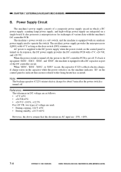
... about 5 min after the power switch is cut off . if charge exists in the capacitor while the power switch is equipped with a DC capacitor as part of various data with +5 V as long as follows: • +5 V ±5% • +24 VR ±5% • +24 VU -10.0%, +12... power supply circuit in which a DC power supply, scanning lamp power supply, and high-voltage power supply are -15%, +10%. 7-4 COPYRIGHT © 1999 CANON INC. CHAPTER 7 EXTERNALS/AUXILIARY MECHANISMS B. When 'E000', 'E001', 'E002', or 'E003' occurs, the capacitor (C123) collects electric charge; In response, ...
... about 5 min after the power switch is cut off . if charge exists in the capacitor while the power switch is equipped with a DC capacitor as part of various data with +5 V as long as follows: • +5 V ±5% • +24 VR ±5% • +24 VU -10.0%, +12... power supply circuit in which a DC power supply, scanning lamp power supply, and high-voltage power supply are -15%, +10%. 7-4 COPYRIGHT © 1999 CANON INC. CHAPTER 7 EXTERNALS/AUXILIARY MECHANISMS B. When 'E000', 'E001', 'E002', or 'E003' occurs, the capacitor (C123) collects electric charge; In response, ...
Service Manual
Page 187
A few of its part removed. 7. COPYRIGHT © 1999 CANON INC. As necessary, cut the harness band. 6. Use the washers where ... 3. As a rule, do not operate the machine with a washer to mount the grounding wire and Varis- CANON PC800s/900s REV.0 AUG. 1999 PRINTED IN JAPAN (IMPRIME AU JAPON) 7-7 Do not use any of the ...screws used to ensure electrical continuity.) 5. Unless otherwise instructed, assemble the parts by type (length, diameter) and location. 4. CHAPTER 7 EXTERNALS/AUXILIARY MECHANISMS III. Before starting the work, turn...
A few of its part removed. 7. COPYRIGHT © 1999 CANON INC. As necessary, cut the harness band. 6. Use the washers where ... 3. As a rule, do not operate the machine with a washer to mount the grounding wire and Varis- CANON PC800s/900s REV.0 AUG. 1999 PRINTED IN JAPAN (IMPRIME AU JAPON) 7-7 Do not use any of the ...screws used to ensure electrical continuity.) 5. Unless otherwise instructed, assemble the parts by type (length, diameter) and location. 4. CHAPTER 7 EXTERNALS/AUXILIARY MECHANISMS III. Before starting the work, turn...

Service Manual
Page 224
...ASSEMBLY As needed, disassemble/assemble the machine with any screws indiscriminately. 8-18 COPYRIGHT © 1999 CANON INC. As a rule, do not operate the machine with the following in mind: 1. ! A few of its part removed. 7. CHAPTER 8 ADF II. Do not use any of the screws used to mount... the grounding wire and Varis- Unless otherwise instructed, assemble the parts by type (length, diameter) and location. 4. Identify the screws by reversing the steps used are special screws (with a washer to ensure electrical...
...ASSEMBLY As needed, disassemble/assemble the machine with any screws indiscriminately. 8-18 COPYRIGHT © 1999 CANON INC. As a rule, do not operate the machine with the following in mind: 1. ! A few of its part removed. 7. CHAPTER 8 ADF II. Do not use any of the screws used to mount... the grounding wire and Varis- Unless otherwise instructed, assemble the parts by type (length, diameter) and location. 4. Identify the screws by reversing the steps used are special screws (with a washer to ensure electrical...
Service Manual
Page 255
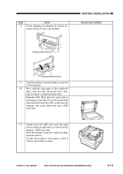
..., as packaging so that it in transit. Step 8 Work Fit the shipping attachments [1] and [2] detached in place to the machine. COPYRIGHT © 1999 CANON INC. CANON PC800s/900s REV.0 AUG. 1999 PRINTED IN JAPAN (IMPRIME AU JAPON) 9-13 CHAPTER 9 INSTALLATION Checks and remarks Shipping attachment [1] Shipping attachment [2] 9 Tape ... close the copyboard cover; then, tape it will not open while in place. (Copyboard type only) Raise the ADF. Then, place two parts used as shown in the diagram. (ADF type only) Pack the machine, using the original packing material and box.
..., as packaging so that it in transit. Step 8 Work Fit the shipping attachments [1] and [2] detached in place to the machine. COPYRIGHT © 1999 CANON INC. CANON PC800s/900s REV.0 AUG. 1999 PRINTED IN JAPAN (IMPRIME AU JAPON) 9-13 CHAPTER 9 INSTALLATION Checks and remarks Shipping attachment [1] Shipping attachment [2] 9 Tape ... close the copyboard cover; then, tape it will not open while in place. (Copyboard type only) Raise the ADF. Then, place two parts used as shown in the diagram. (ADF type only) Pack the machine, using the original packing material and box.
Service Manual
Page 257
SCHEDULED SERVICING ....... 10-1 IV. PERIODICALLY REPLACED PARTS 10-1 II. CHAPTER 10 MAINTENANCE AND SERVICING I. STORING AND HANDLING THE CARTRIDGE 10-2 A. Storing and Handling the Cartridge with the Packaging Seal Intact ........ 10-2 B. CANON PC800s/900s REV.0 AUG. 1999 PRINTED IN JAPAN (IMPRIME AU JAPON) DURABLES AND CONSUMABLES 10-1 III. Storing the Cartridge with the Packaging Seal Removed 10-3 COPYRIGHT © 1999 CANON INC.
SCHEDULED SERVICING ....... 10-1 IV. PERIODICALLY REPLACED PARTS 10-1 II. CHAPTER 10 MAINTENANCE AND SERVICING I. STORING AND HANDLING THE CARTRIDGE 10-2 A. Storing and Handling the Cartridge with the Packaging Seal Intact ........ 10-2 B. CANON PC800s/900s REV.0 AUG. 1999 PRINTED IN JAPAN (IMPRIME AU JAPON) DURABLES AND CONSUMABLES 10-1 III. Storing the Cartridge with the Packaging Seal Removed 10-3 COPYRIGHT © 1999 CANON INC.
Service Manual
Page 258
DURABLES AND CONSUMABLES The machine does not have parts which require scheduled servicing. COPYRIGHT © 1999 CANON INC. CHAPTER 10 MAINTENANCE AND SERVICING I. II. SCHEDULED SERVICING The machine does not have any parts which must be replaced on a periodical basis. PERIODICALLY REPLACED PARTS The machine does not have items designated as durables or consumables. CANON PC800s/900s REV.0 AUG. 1999 PRINTED IN JAPAN (IMPRIME AU JAPON) 10-1 III.
DURABLES AND CONSUMABLES The machine does not have parts which require scheduled servicing. COPYRIGHT © 1999 CANON INC. CHAPTER 10 MAINTENANCE AND SERVICING I. II. SCHEDULED SERVICING The machine does not have any parts which must be replaced on a periodical basis. PERIODICALLY REPLACED PARTS The machine does not have items designated as durables or consumables. CANON PC800s/900s REV.0 AUG. 1999 PRINTED IN JAPAN (IMPRIME AU JAPON) 10-1 III.


