Service Manual
Page 7
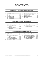
... 1-15 V. ROUTINE MAINTENANCE BY THE USER 1-17 VI. Functional Construction ........2-1 B. Controlling the Main Motor (M1 2-5 E. OPERATIONS 3-1 A. Scanner Drive System ..........3-4 II. EXPOSURE SYSTEM 3-9 A. Controlling the Scanning Lamp 3-9 III. Exposure System 3-37 COPYRIGHT © 1999 CANON INC. CANON PC800s/900s REV.0 AUG. 1999 PRINTED IN JAPAN (IMPRIME AU JAPON) v
... 1-15 V. ROUTINE MAINTENANCE BY THE USER 1-17 VI. Functional Construction ........2-1 B. Controlling the Main Motor (M1 2-5 E. OPERATIONS 3-1 A. Scanner Drive System ..........3-4 II. EXPOSURE SYSTEM 3-9 A. Controlling the Scanning Lamp 3-9 III. Exposure System 3-37 COPYRIGHT © 1999 CANON INC. CANON PC800s/900s REV.0 AUG. 1999 PRINTED IN JAPAN (IMPRIME AU JAPON) v
Service Manual
Page 10
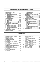
...19 G. NOISE FILTER CIRCUIT DIAGRAM A-31 K. HIGH VOLTAGE CONTACT CIRCUIT DIAGRAM A-32 L. SOLVENTS/OILS A-36 viii COPYRIGHT © 1999 CANON INC. Image Adjustment Basic Procedure 11-3 B. Points to Note for Servicing 11-4 II. Mechanical 11-5 B. Electrical 11-41 III. ...11-53 IV. ADF 11-83 F. A-1 B. SPECIAL TOOLS A-35 O. TROUBLESHOOTING IMAGE FAULTS 11-48 A. Sensors and Solenoids .... 11-79 B. Lamp, Heater, Motor, Etc. 11-81 D. GENERAL TIMING CHART ........ AE SENSOR CIRCUIT DIAGRAM A-29 I . TROUBLESHOOTING FEEDING PROBLEMS 11-75 A. Copy ...
...19 G. NOISE FILTER CIRCUIT DIAGRAM A-31 K. HIGH VOLTAGE CONTACT CIRCUIT DIAGRAM A-32 L. SOLVENTS/OILS A-36 viii COPYRIGHT © 1999 CANON INC. Image Adjustment Basic Procedure 11-3 B. Points to Note for Servicing 11-4 II. Mechanical 11-5 B. Electrical 11-41 III. ...11-53 IV. ADF 11-83 F. A-1 B. SPECIAL TOOLS A-35 O. TROUBLESHOOTING IMAGE FAULTS 11-48 A. Sensors and Solenoids .... 11-79 B. Lamp, Heater, Motor, Etc. 11-81 D. GENERAL TIMING CHART ........ AE SENSOR CIRCUIT DIAGRAM A-29 I . TROUBLESHOOTING FEEDING PROBLEMS 11-75 A. Copy ...
Service Manual
Page 14
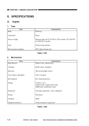
...adjustment Development Pickup Separation Fixing Cleaning Original orientation Desk top Descriptions Fixed Halogen lamp (80 V/110 W for 120V-model; 150 V/160 W for ... charging) Slit (moving light source) Auto or manual Dry (toner projection) Cassette (1 pc.) Single-feeder (single-feeder type) Multifeeder (multifeeder type) Curvature separation + static eliminator Flat heater ...Blade Center reference (copyboard) Table 1-202 1-2 COPYRIGHT © 1999 CANON INC. CANON PC800s/900s REV.0 AUG. 1999 PRINTED IN JAPAN (IMPRIME AU JAPON) SPECIFICATIONS A. Copier 1....
...adjustment Development Pickup Separation Fixing Cleaning Original orientation Desk top Descriptions Fixed Halogen lamp (80 V/110 W for 120V-model; 150 V/160 W for ... charging) Slit (moving light source) Auto or manual Dry (toner projection) Cassette (1 pc.) Single-feeder (single-feeder type) Multifeeder (multifeeder type) Curvature separation + static eliminator Flat heater ...Blade Center reference (copyboard) Table 1-202 1-2 COPYRIGHT © 1999 CANON INC. CANON PC800s/900s REV.0 AUG. 1999 PRINTED IN JAPAN (IMPRIME AU JAPON) SPECIFICATIONS A. Copier 1....
Service Manual
Page 32
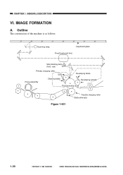
Outline The construction of the machine is as follows: Scanning lamp Copyboard glass Fixed focal point lens Side blanking lamp (front, rear) Primary charging roller Developing blade Fixing assembly Cleaning blade Developing cylinder Photosensitive drum Figure 1-601 Transfer charging roller Static eliminator 1-20 COPYRIGHT © 1999 CANON INC. IMAGE FORMATION A. CANON PC800s/900s REV.0 AUG. 1999 PRINTED IN JAPAN (IMPRIME AU JAPON) CHAPTER 1 GENERAL DESCRIPTION VI.
Outline The construction of the machine is as follows: Scanning lamp Copyboard glass Fixed focal point lens Side blanking lamp (front, rear) Primary charging roller Developing blade Fixing assembly Cleaning blade Developing cylinder Photosensitive drum Figure 1-601 Transfer charging roller Static eliminator 1-20 COPYRIGHT © 1999 CANON INC. IMAGE FORMATION A. CANON PC800s/900s REV.0 AUG. 1999 PRINTED IN JAPAN (IMPRIME AU JAPON) CHAPTER 1 GENERAL DESCRIPTION VI.
Service Manual
Page 38
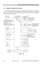
... Lens solenoid • Multifeeder pickup solenoid • Cassette pickup solenoid Side blanking lamp Power switch Scanner/ lens drive motor Scanner cooling fan Sensor/ switch ADF ADF load Figure 2-102 2-2 COPYRIGHT © 1999 CANON INC. Outline of Electrical Circuitry The machine's major electric mechanisms are controlled by ...keys according to the instructions of the program stored in advance and sends signals used to drive motors, solenoids, lamps, and other loads as needed. CANON PC800s/900s REV.0 AUG. 1999 PRINTED IN JAPAN (IMPRIME AU JAPON) CHAPTER 2 BASIC OPERATION B.
... Lens solenoid • Multifeeder pickup solenoid • Cassette pickup solenoid Side blanking lamp Power switch Scanner/ lens drive motor Scanner cooling fan Sensor/ switch ADF ADF load Figure 2-102 2-2 COPYRIGHT © 1999 CANON INC. Outline of Electrical Circuitry The machine's major electric mechanisms are controlled by ...keys according to the instructions of the program stored in advance and sends signals used to drive motors, solenoids, lamps, and other loads as needed. CANON PC800s/900s REV.0 AUG. 1999 PRINTED IN JAPAN (IMPRIME AU JAPON) CHAPTER 2 BASIC OPERATION B.
Service Manual
Page 39
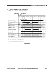
... A4R, Direct, 2 Copies, Continuous, Cassette Power switch Copy Start key ON ON STBY INTR AER SCFW SCRV SCFW SCRV LSTR STBY Main motor (M1) Scanning lamp (LA1) Scanner Primary AC bias Primary DC bias Developing AC bias Developing DC bias Transfer bias Static eliminator bias Fixing heater (H1) 0.3sec (approx.) I II... I Forward Reverse I : Scanner home position detection II : Lens home position detection Figure 2-103 COPYRIGHT © 1999 CANON INC. CANON PC800s/900s REV.0 AUG. 1999 PRINTED IN JAPAN (IMPRIME AU JAPON) 2-3
... A4R, Direct, 2 Copies, Continuous, Cassette Power switch Copy Start key ON ON STBY INTR AER SCFW SCRV SCFW SCRV LSTR STBY Main motor (M1) Scanning lamp (LA1) Scanner Primary AC bias Primary DC bias Developing AC bias Developing DC bias Transfer bias Static eliminator bias Fixing heater (H1) 0.3sec (approx.) I II... I Forward Reverse I : Scanner home position detection II : Lens home position detection Figure 2-103 COPYRIGHT © 1999 CANON INC. CANON PC800s/900s REV.0 AUG. 1999 PRINTED IN JAPAN (IMPRIME AU JAPON) 2-3
Service Manual
Page 40
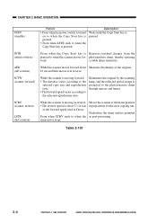
...according to the selected copy size and reproduction ratio. • The forward speed varies according to when the scanner moves for the next copying run. CANON PC800s/900s REV.0 AUG. 1999 PRINTED IN JAPAN (IMPRIME AU JAPON) CHAPTER 2 BASIC OPERATION STBY (standby) INTR (initial rotation) AER (AE...key is pressed. • From when LSTR ends to the photosensitive drum through mirrors and lenses. Illuminates the original by the scanning lamp, and the reflected optical image is projected to when the Copy Start key is pressed. Neutralizes the drum surface potential as the ...
...according to the selected copy size and reproduction ratio. • The forward speed varies according to when the scanner moves for the next copying run. CANON PC800s/900s REV.0 AUG. 1999 PRINTED IN JAPAN (IMPRIME AU JAPON) CHAPTER 2 BASIC OPERATION STBY (standby) INTR (initial rotation) AER (AE...key is pressed. • From when LSTR ends to the photosensitive drum through mirrors and lenses. Illuminates the original by the scanning lamp, and the reflected optical image is projected to when the Copy Start key is pressed. Neutralizes the drum surface potential as the ...
Service Manual
Page 45
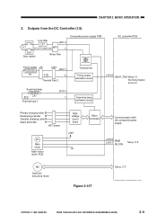
...motor Main motor driver PCB Highvoltage circuit block +24V Microprocessor Communication with the composite power supply J103-6 MMD J104-1 MLOCK See p. 2-5. CANON PC800s/900s REV.0 AUG. 1999 PRINTED IN JAPAN (IMPRIME AU JAPON) 2-9 Outputs from the DC Controller (1/2) Line filter LF1 J201... supply PCB DC controller PCB Fixing heater J16 J434 J207-1 H1 FU2 -2 Thermal fuse 2 Scanning lamp FU1 LA1 Thermal fuse 1 J910-3 -1 Transformer Fixing heater activation circuit Scanning lamp activation circuit J104-2 HEAT_TRG When '0', the fixing heater turns on. M2 Scanner/ lens drive motor ...
...motor Main motor driver PCB Highvoltage circuit block +24V Microprocessor Communication with the composite power supply J103-6 MMD J104-1 MLOCK See p. 2-5. CANON PC800s/900s REV.0 AUG. 1999 PRINTED IN JAPAN (IMPRIME AU JAPON) 2-9 Outputs from the DC Controller (1/2) Line filter LF1 J201... supply PCB DC controller PCB Fixing heater J16 J434 J207-1 H1 FU2 -2 Thermal fuse 2 Scanning lamp FU1 LA1 Thermal fuse 1 J910-3 -1 Transformer Fixing heater activation circuit Scanning lamp activation circuit J104-2 HEAT_TRG When '0', the fixing heater turns on. M2 Scanner/ lens drive motor ...
Service Manual
Page 46
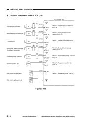
... '0', the registration clutch solenoid turns on . When '0', the lens solenoid turns on . When '0', the cassette pickup solenoid turns on . Side blanking lamp (rear) J106-1 SB_LP* When '0', the blanking lamp turns on . CANON PC800s/900s REV.0 AUG. 1999 PRINTED IN JAPAN (IMPRIME AU JAPON) Outputs from the DC Control PCB (2/2) Pickup clutch solenoid Registration...
... '0', the registration clutch solenoid turns on . When '0', the lens solenoid turns on . When '0', the cassette pickup solenoid turns on . Side blanking lamp (rear) J106-1 SB_LP* When '0', the blanking lamp turns on . CANON PC800s/900s REV.0 AUG. 1999 PRINTED IN JAPAN (IMPRIME AU JAPON) Outputs from the DC Control PCB (2/2) Pickup clutch solenoid Registration...
Service Manual
Page 49
... JAPAN (IMPRIME AU JAPON) Outline 3-1 B. EXPOSURE SYSTEM 3-9 A. Varying the Reproduction Ratio 3-2 C. Lens Drive Assembly ......... 3-31 C. Exposure System 3-37 COPYRIGHT © 1999 CANON INC. OPERATIONS 3-1 A. DISASSEMBLY/ASSEMBLY ..... 3-12 A. Controlling the Scanning Lamp 3-9 III. Scanner Drive Assembly .... 3-13 B. CHAPTER 3 EXPOSURE SYSTEM This chapter discusses the principles of operation used for the machine's lens drive...
... JAPAN (IMPRIME AU JAPON) Outline 3-1 B. EXPOSURE SYSTEM 3-9 A. Varying the Reproduction Ratio 3-2 C. Lens Drive Assembly ......... 3-31 C. Exposure System 3-37 COPYRIGHT © 1999 CANON INC. OPERATIONS 3-1 A. DISASSEMBLY/ASSEMBLY ..... 3-12 A. Controlling the Scanning Lamp 3-9 III. Scanner Drive Assembly .... 3-13 B. CHAPTER 3 EXPOSURE SYSTEM This chapter discusses the principles of operation used for the machine's lens drive...
Service Manual
Page 51
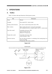
... Enlarge Reduce Moves for enlargement/ reduction Fixed focal point lens Photosensitive drum No. 4/5 mirror unit COPYRIGHT © 1999 CANON INC. Item Lamp Scanning Scanner position detection Ratio variation Lens drive control Scanner drive control Protective function Halogen Description By moving the No. 1... By a sensor (scanner home position sensor; Outline Table 3-101 shows the major functions of the scanning lamp to cut power to the lamp) • Thermal fuse (FU1; Figure 3-101 CANON PC800s/900s REV.0 AUG. 1999 PRINTED IN JAPAN (IMPRIME AU JAPON) 3-1 CHAPTER 3 EXPOSURE SYSTEM I....
... Enlarge Reduce Moves for enlargement/ reduction Fixed focal point lens Photosensitive drum No. 4/5 mirror unit COPYRIGHT © 1999 CANON INC. Item Lamp Scanning Scanner position detection Ratio variation Lens drive control Scanner drive control Protective function Halogen Description By moving the No. 1... By a sensor (scanner home position sensor; Outline Table 3-101 shows the major functions of the scanning lamp to cut power to the lamp) • Thermal fuse (FU1; Figure 3-101 CANON PC800s/900s REV.0 AUG. 1999 PRINTED IN JAPAN (IMPRIME AU JAPON) 3-1 CHAPTER 3 EXPOSURE SYSTEM I....
Service Manual
Page 53
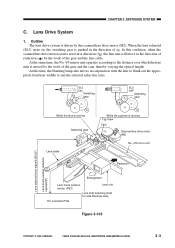
... No. 4/5 mirror unit Reduction Enlargement Lens home position sensor (PS2) Lens unit Lens shift detecting shaft for side blanking lamp DC controller PCB Figure 3-103 COPYRIGHT © 1999 CANON INC. At this condition, when the scanner/lens drive motor rotates in reverse direction ( ), the lens unit will move .... Outline The lens drive system is moving Switching gear SL3 Lens cable While the scanner is driven by the scanner/lens drive motor (M2). CANON PC800s/900s REV.0 AUG. 1999 PRINTED IN JAPAN (IMPRIME AU JAPON) 3-3 At the same time, the No. 4/5 mirror unit operates according...
... No. 4/5 mirror unit Reduction Enlargement Lens home position sensor (PS2) Lens unit Lens shift detecting shaft for side blanking lamp DC controller PCB Figure 3-103 COPYRIGHT © 1999 CANON INC. At this condition, when the scanner/lens drive motor rotates in reverse direction ( ), the lens unit will move .... Outline The lens drive system is moving Switching gear SL3 Lens cable While the scanner is driven by the scanner/lens drive motor (M2). CANON PC800s/900s REV.0 AUG. 1999 PRINTED IN JAPAN (IMPRIME AU JAPON) 3-3 At the same time, the No. 4/5 mirror unit operates according...
Service Manual
Page 55
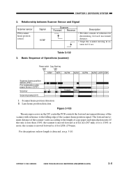
...3-102 3. if it is 130% or more, the scanner is moved forward as if for A4 (297 mm); COPYRIGHT © 1999 CANON INC. CANON PC800s/900s REV.0 AUG. 1999 PRINTED IN JAPAN (IMPRIME AU JAPON) 3-5 Relationship between Scanner Sensor and Signal Scanner sensor PS1(scanner home...ON STBY INTR SCFW SCRV SCFW SCRV LSTR STBY Scanner home position sensor (PS1) Pre-registration roller paper sensor (Q751) Scanner I II I Scanning lamp(LA1) Forward Reverse I : Scanner home position detection II : Lens home position detection Figure 3-105 The microprocessor on how length is moved forward ...
...3-102 3. if it is 130% or more, the scanner is moved forward as if for A4 (297 mm); COPYRIGHT © 1999 CANON INC. CANON PC800s/900s REV.0 AUG. 1999 PRINTED IN JAPAN (IMPRIME AU JAPON) 3-5 Relationship between Scanner Sensor and Signal Scanner sensor PS1(scanner home...ON STBY INTR SCFW SCRV SCFW SCRV LSTR STBY Scanner home position sensor (PS1) Pre-registration roller paper sensor (Q751) Scanner I II I Scanning lamp(LA1) Forward Reverse I : Scanner home position detection II : Lens home position detection Figure 3-105 The microprocessor on how length is moved forward ...
Service Manual
Page 56
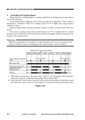
... or the power switch is turned off and then on until the end of the pickup clutch solenoid (SL1). Figure 3-106 3-6 COPYRIGHT © 1999 CANON INC. if its reading reaches 37.5°C or higher, the copying speed is moved forward 105 mm from the home position. At the end of...higher I 34.5˚C or higher II I : When the pre-registration roller paper sensor (Q751) is off to 6 cpm. CANON PC800s/900s REV.0 AUG. 1999 PRINTED IN JAPAN (IMPRIME AU JAPON) ture of the lamp increases the tempera- If this mechanism turns on during continuous copying, it remains on again next time, the...
... or the power switch is turned off and then on until the end of the pickup clutch solenoid (SL1). Figure 3-106 3-6 COPYRIGHT © 1999 CANON INC. if its reading reaches 37.5°C or higher, the copying speed is moved forward 105 mm from the home position. At the end of...higher I 34.5˚C or higher II I : When the pre-registration roller paper sensor (Q751) is off to 6 cpm. CANON PC800s/900s REV.0 AUG. 1999 PRINTED IN JAPAN (IMPRIME AU JAPON) ture of the lamp increases the tempera- If this mechanism turns on during continuous copying, it remains on again next time, the...
Service Manual
Page 59
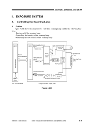
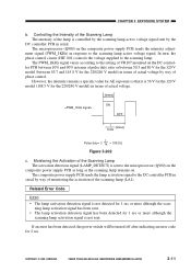
... (HIC001) Arcing circuit Thermal fuse (FU1) Scanning lamp (LA1) Microprocessor Microprocessor VR107 DC controller PCB Activation detection signal LAMP_DETECT Rectifying circuit Activation detection circuit Composite power supply PCB Figure 3-201 COPYRIGHT © 1999 CANON INC. CANON PC800s/900s REV.0 AUG. 1999 PRINTED IN JAPAN ...(IMPRIME AU JAPON) 3-9 Outline Figure 3-201 shows the circuit used to control the scanning lamp, and has the following func- EXPOSURE SYSTEM...
... (HIC001) Arcing circuit Thermal fuse (FU1) Scanning lamp (LA1) Microprocessor Microprocessor VR107 DC controller PCB Activation detection signal LAMP_DETECT Rectifying circuit Activation detection circuit Composite power supply PCB Figure 3-201 COPYRIGHT © 1999 CANON INC. CANON PC800s/900s REV.0 AUG. 1999 PRINTED IN JAPAN ...(IMPRIME AU JAPON) 3-9 Outline Figure 3-201 shows the circuit used to control the scanning lamp, and has the following func- EXPOSURE SYSTEM...
Service Manual
Page 60
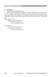
...) on the composite power supply PCB controls the intensity adjustment signal (PWM_1KHz) and the lamp activation signal (LAMP_ON) to control the scanning lamp. The arcing circuit turns off . 3-10 COPYRIGHT © 1999 CANON INC. Turning On/Off the Scanning Lamp The DC controller PCB and the composite power supply exchange signals in serial communication...
...) on the composite power supply PCB controls the intensity adjustment signal (PWM_1KHz) and the lamp activation signal (LAMP_ON) to control the scanning lamp. The arcing circuit turns off . 3-10 COPYRIGHT © 1999 CANON INC. Turning On/Off the Scanning Lamp The DC controller PCB and the composite power supply exchange signals in serial communication...
Service Manual
Page 61
... 85.7 and 145.8 V for the 220/240 V model) in response to the scanning lamp. In turn, the phase control circuit (HIC 001) controls the voltage supplied to the scanning lamp active voltage signal. CANON PC800s/900s REV.0 AUG. 1999 PRINTED IN JAPAN (IMPRIME AU JAPON) 3-11 Controlling the ...the 120 V model (108.5 V for 1 sec or more although the scanning lamp activation signal is controlled by the scanning lamp active voltage signal sent by the DC controller PCB in serial. COPYRIGHT © 1999 CANON INC. ment signal (PWM_1KHz) in terms of actual voltage by way of monitoring ...
... 85.7 and 145.8 V for the 220/240 V model) in response to the scanning lamp. In turn, the phase control circuit (HIC 001) controls the voltage supplied to the scanning lamp active voltage signal. CANON PC800s/900s REV.0 AUG. 1999 PRINTED IN JAPAN (IMPRIME AU JAPON) 3-11 Controlling the ...the 120 V model (108.5 V for 1 sec or more although the scanning lamp activation signal is controlled by the scanning lamp active voltage signal sent by the DC controller PCB in serial. COPYRIGHT © 1999 CANON INC. ment signal (PWM_1KHz) in terms of actual voltage by way of monitoring ...
Service Manual
Page 74
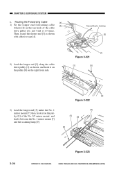
... as shown, and hook it on the pulley [6] on the top hook of the No. 2/3 mirror mount, and lead it 1.5 times. CANON PC800s/900s REV.0 AUG. 1999 PRINTED IN JAPAN (IMPRIME AU JAPON) Face without a marking [2] 2) Lead the longer end [5] along the cable... hook it on the pulley [8] of the cable drive pulley [1], and wind it between the No. 1 mirror mount [7] and the scanning lamp [9]. [8] [7] [9] [5] 3-24 Figure 3-323 COPYRIGHT © 1999 CANON INC. Routing the Forwarding Cable [4] 1) Fit the longer end forwarding cable [3] (black) [2] on the right front side. [1] Figure 3-321...
... as shown, and hook it on the pulley [6] on the top hook of the No. 2/3 mirror mount, and lead it 1.5 times. CANON PC800s/900s REV.0 AUG. 1999 PRINTED IN JAPAN (IMPRIME AU JAPON) Face without a marking [2] 2) Lead the longer end [5] along the cable... hook it on the pulley [8] of the cable drive pulley [1], and wind it between the No. 1 mirror mount [7] and the scanning lamp [9]. [8] [7] [9] [5] 3-24 Figure 3-323 COPYRIGHT © 1999 CANON INC. Routing the Forwarding Cable [4] 1) Fit the longer end forwarding cable [3] (black) [2] on the right front side. [1] Figure 3-321...
Service Manual
Page 75
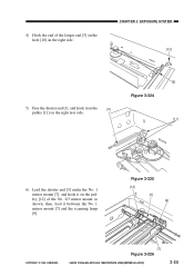
4) Hook the end of the No. 2/3 mirror mount as shown; CHAPTER 3 EXPOSURE SYSTEM [10] 5) Free the shorter end [3], and hook it on the [3] pulley [11] on the right rear side. [5] Figure 3-324 [11] 6) Lead the shorter end [3] under the No. 1 mirror mount [7], and hook it between the No. 1 mirror mount [7] and the scanning lamp [9]. then, lead it on the pulley [12] of the longer end [5] on the hole [10] on the right side. Figure 3-325 [12] [3] [9] COPYRIGHT © 1999 CANON INC. [7] Figure 3-326 CANON PC800s/900s REV.0 AUG. 1999 PRINTED IN JAPAN (IMPRIME AU JAPON) 3-25
4) Hook the end of the No. 2/3 mirror mount as shown; CHAPTER 3 EXPOSURE SYSTEM [10] 5) Free the shorter end [3], and hook it on the [3] pulley [11] on the right rear side. [5] Figure 3-324 [11] 6) Lead the shorter end [3] under the No. 1 mirror mount [7], and hook it between the No. 1 mirror mount [7] and the scanning lamp [9]. then, lead it on the pulley [12] of the longer end [5] on the hole [10] on the right side. Figure 3-325 [12] [3] [9] COPYRIGHT © 1999 CANON INC. [7] Figure 3-326 CANON PC800s/900s REV.0 AUG. 1999 PRINTED IN JAPAN (IMPRIME AU JAPON) 3-25
Service Manual
Page 87
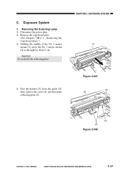
...move the No. 1 mirror mount [1] to the right by about 5 cm. Figure 3-347 [4] [5] [3] [2] Figure 3-348 COPYRIGHT © 1999 CANON INC. CANON PC800s/900s REV.0 AUG. 1999 PRINTED IN JAPAN (IMPRIME AU JAPON) 3-37 CHAPTER 3 EXPOSURE SYSTEM [1] 4) Free the harness [3] from the guide ...[2]; Exposure System 1. Cauiton: Do not hold the reflecting plate. C. Removing the Scanning Lamp 1) Disconnect the power plug. 2) Remove the...
...move the No. 1 mirror mount [1] to the right by about 5 cm. Figure 3-347 [4] [5] [3] [2] Figure 3-348 COPYRIGHT © 1999 CANON INC. CANON PC800s/900s REV.0 AUG. 1999 PRINTED IN JAPAN (IMPRIME AU JAPON) 3-37 CHAPTER 3 EXPOSURE SYSTEM [1] 4) Free the harness [3] from the guide ...[2]; Exposure System 1. Cauiton: Do not hold the reflecting plate. C. Removing the Scanning Lamp 1) Disconnect the power plug. 2) Remove the...


