
Users Manual - English
Page 82
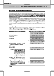
... to register a distinctive ringing number with your distinctive ringing number, press the Start key and check that the ringing pattern is in two parts: First, you begin this function: 1. Press Set. 6. This procedure is the one -time procedure to call the distinctive ringing number ... friend to find the SET mode. 5. Press 6. 3. NOTE: The display should say D/R SET MODE. Then pick up the fax handset. 3550-US-5.0 DISTINCTIVE RINGING RECEIVING FAXES AND OTHER CALLS Setting the Distinctive Ringing Function This function is , wait (at least two ring cycles) until the ...
... to register a distinctive ringing number with your distinctive ringing number, press the Start key and check that the ringing pattern is in two parts: First, you begin this function: 1. Press Set. 6. This procedure is the one -time procedure to call the distinctive ringing number ... friend to find the SET mode. 5. Press 6. 3. NOTE: The display should say D/R SET MODE. Then pick up the fax handset. 3550-US-5.0 DISTINCTIVE RINGING RECEIVING FAXES AND OTHER CALLS Setting the Distinctive Ringing Function This function is , wait (at least two ring cycles) until the ...
Users Manual - English
Page 109
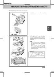
... Inside of the machine will be extremely HOT! So, never touch the shaded parts shown in the left illustration. WARNING Just after you have used the machine, some internal parts of the machine 2) Open the top cover. HOT ! 12-2 3550-US-5.0 REPLACING THE TONER CARTRIDGE AND DRUM UNIT Follow these steps to avoid spilling...
... Inside of the machine will be extremely HOT! So, never touch the shaded parts shown in the left illustration. WARNING Just after you have used the machine, some internal parts of the machine 2) Open the top cover. HOT ! 12-2 3550-US-5.0 REPLACING THE TONER CARTRIDGE AND DRUM UNIT Follow these steps to avoid spilling...
Users Manual - English
Page 112
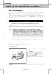
... is nearly at approximately 20,000 pages. The actual number of pages per job. For best performance, use and the number of pages your drum. 3550-US-5.0 REPLACING THE TONER CARTRIDGE AND DRUM UNIT Replacing the Drum Unit The machine uses a drum unit to replace the current one. So please be...
... is nearly at approximately 20,000 pages. The actual number of pages per job. For best performance, use and the number of pages your drum. 3550-US-5.0 REPLACING THE TONER CARTRIDGE AND DRUM UNIT Replacing the Drum Unit The machine uses a drum unit to replace the current one. So please be...

Users Manual - English
Page 116
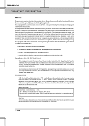
3550-US-5.0 REGULAR MAINTENANCE AND TROUBLESHOOTING WARNING • Donotuseisopropylalcoholtocleanthescannerwindoworthetonersensor. • Donottouchthescannerwindowwithyourfinger. • Handle the drum unit carefully because it off with cold water. .... Gears Tonner sensor Electric terminal Gears Scanner window Shaded parts are extremelyHOT! Home Position ( ) Tab 13-2 corona wire Inside the machine WARNING Just after you have used the fax machine, some internal parts of the machine, never touch the shaded parts shown in the diagram to avoid spilling and scattering the...
3550-US-5.0 REGULAR MAINTENANCE AND TROUBLESHOOTING WARNING • Donotuseisopropylalcoholtocleanthescannerwindoworthetonersensor. • Donottouchthescannerwindowwithyourfinger. • Handle the drum unit carefully because it off with cold water. .... Gears Tonner sensor Electric terminal Gears Scanner window Shaded parts are extremelyHOT! Home Position ( ) Tab 13-2 corona wire Inside the machine WARNING Just after you have used the fax machine, some internal parts of the machine, never touch the shaded parts shown in the diagram to avoid spilling and scattering the...

Users Manual - English
Page 131
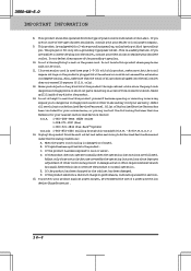
...connect to determine the quantity of your equipment. The REN is useful to your IntelliFAX3550, contact Brother service personnel at 1-800-284-4FAX(Voice)(U.S.A.Only). 1-908-271-1937 (Fax) (U.S.A. Your...you will be connected to emergency numbers: • Remain on obtaining service or repair. 3550-US-5.0 IMPORTANT INFORMATION 14. When programming emergency numbers and/or making test calls to the... damages the telephone network, the telephone company may ask that the equipment is Part 68 compliant. IMPORTANT INFORMATION Standard Telephone and FCC Notices (Applies only to 120V...
...connect to determine the quantity of your equipment. The REN is useful to your IntelliFAX3550, contact Brother service personnel at 1-800-284-4FAX(Voice)(U.S.A.Only). 1-908-271-1937 (Fax) (U.S.A. Your...you will be connected to emergency numbers: • Remain on obtaining service or repair. 3550-US-5.0 IMPORTANT INFORMATION 14. When programming emergency numbers and/or making test calls to the... damages the telephone network, the telephone company may ask that the equipment is Part 68 compliant. IMPORTANT INFORMATION Standard Telephone and FCC Notices (Applies only to 120V...
Users Manual - English
Page 132
...installation. Compliance is certified as a Class I laser product under the U.S. FDA Regulations U.S. 3550-US-5.0 IMPORTANT INFORMATION Warning For protection against harmful interference in a residential installation. Laser Safety... Department of Health and Human Services (DHHS) Radiation Performance Standard according to Part 15 of procedures other than those specified in this equipment does cause harmful ..., which can be used in hazardous invisible radiation exposure. 14-2 MANUFACTURED : BROTHER INDUSTRIES, LTD. 15-1 Naeshiro-cho Mizuho-ku Nagoya, 467 Japan This product...
...installation. Compliance is certified as a Class I laser product under the U.S. FDA Regulations U.S. 3550-US-5.0 IMPORTANT INFORMATION Warning For protection against harmful interference in a residential installation. Laser Safety... Department of Health and Human Services (DHHS) Radiation Performance Standard according to Part 15 of procedures other than those specified in this equipment does cause harmful ..., which can be used in hazardous invisible radiation exposure. 14-2 MANUFACTURED : BROTHER INDUSTRIES, LTD. 15-1 Naeshiro-cho Mizuho-ku Nagoya, 467 Japan This product...
Users Manual - English
Page 134
...plug will often require extensive work by the operating instructions since they may touch dangerous voltage points or short out parts resulting in damage and will fit only into the wall outlet does not exceed 15 amperes (U.S.A. Do not ...a power protection device (Surge Protector). 14-4 E. If the product has been dropped or the cabinet has been damaged. 3550-US-5.0 IMPORTANT INFORMATION 8. UnplugthisproductfromthewalloutletandreferservicingtoAuthorizedServicePersonnel under the following Customer Service Numbers for your nearest Authorized Service Center: U.S.A. 1-800-284-4FAX...
...plug will often require extensive work by the operating instructions since they may touch dangerous voltage points or short out parts resulting in damage and will fit only into the wall outlet does not exceed 15 amperes (U.S.A. Do not ...a power protection device (Surge Protector). 14-4 E. If the product has been dropped or the cabinet has been damaged. 3550-US-5.0 IMPORTANT INFORMATION 8. UnplugthisproductfromthewalloutletandreferservicingtoAuthorizedServicePersonnel under the following Customer Service Numbers for your nearest Authorized Service Center: U.S.A. 1-800-284-4FAX...

Service Manual
Page 2
© Copyright Brother 1998 All rights reserved. Specifications are subject to change without permission in writing from the publisher. No part of this publication may be reproduced in any form or by any means without notice.
© Copyright Brother 1998 All rights reserved. Specifications are subject to change without permission in writing from the publisher. No part of this publication may be reproduced in any form or by any means without notice.
Service Manual
Page 3
... for the customer, the service personnel must adequately understand and apply this manual. CHAPTER V. CHAPTER IV. CHAPTER VI. This manual is made up of the Brother facsimile equipment. The specifications and functions are subject to rapidly repair the equipment and order any necessary spare...
... for the customer, the service personnel must adequately understand and apply this manual. CHAPTER V. CHAPTER IV. CHAPTER VI. This manual is made up of the Brother facsimile equipment. The specifications and functions are subject to rapidly repair the equipment and order any necessary spare...
Service Manual
Page 22
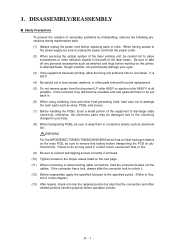
... Document feeding and ejecting mechanism Document scanning mechanism 2nd mirror Document front sensor actuator Document take-in roller ASSY, separation roller ASSY, ADF parts and nip-related parts) feeds those documents into the lens which consists of the document take-in roller ASSY Separation roller ASSY Document rear sensor actuator CCD unit...
... Document feeding and ejecting mechanism Document scanning mechanism 2nd mirror Document front sensor actuator Document take-in roller ASSY, separation roller ASSY, ADF parts and nip-related parts) feeds those documents into the lens which consists of the document take-in roller ASSY Separation roller ASSY Document rear sensor actuator CCD unit...

Service Manual
Page 45
... the loop current. • If the facsimile equipment has an automatic answering facility (TAD), the NCU should be invariant by selecting the constants of the parts in this circuit so as to conform to the communications regulations or codes of each other in the direct current band.
... the loop current. • If the facsimile equipment has an automatic answering facility (TAD), the NCU should be invariant by selecting the constants of the parts in this circuit so as to conform to the communications regulations or codes of each other in the direct current band.
Service Manual
Page 51
... charged in your eyes. (3) If the equipment has been printing, allow the fixing unit sufficient time to take care not to damage the resin parts such as wires, PCBs, and covers. (7) Before handling the PCBs, touch a metal portion of the laser beam. Once removed, they will ...before transporting the PCB (in this chapter.) (13) After repairs, check not only the repaired portion but also that the connectors and other parts removed for parts replacement. (5) Do not remove gears from the power outlet. (2) When servicing the optical system of secondary problems by mishandling, observe the ...
... charged in your eyes. (3) If the equipment has been printing, allow the fixing unit sufficient time to take care not to damage the resin parts such as wires, PCBs, and covers. (7) Before handling the PCBs, touch a metal portion of the laser beam. Once removed, they will ...before transporting the PCB (in this chapter.) (13) After repairs, check not only the repaired portion but also that the connectors and other parts removed for parts replacement. (5) Do not remove gears from the power outlet. (2) When servicing the optical system of secondary problems by mishandling, observe the ...
Service Manual
Page 53
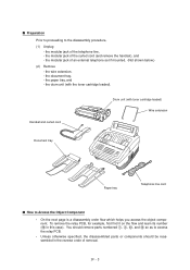
IV - 3 s Preparation Prior to proceeding to access the relay PCB. • Unless otherwise specified, the disassembled parts or components should be reassembled in this case). the modular jack of an external telephone set if mounted. (Not shown below.) (2) Remove - the modular jack ... the curled cord (and remove the handset), and - the document tray, - Handset and curled cord Drum unit (with the toner cartridge loaded). You should remove parts numbered 1, 3, B, and E so as to the disassembly procedure, (1) Unplug - the modular jack of removal.
IV - 3 s Preparation Prior to proceeding to access the relay PCB. • Unless otherwise specified, the disassembled parts or components should be reassembled in this case). the modular jack of an external telephone set if mounted. (Not shown below.) (2) Remove - the modular jack ... the curled cord (and remove the handset), and - the document tray, - Handset and curled cord Drum unit (with the toner cartridge loaded). You should remove parts numbered 1, 3, B, and E so as to the disassembly procedure, (1) Unplug - the modular jack of removal.
Service Manual
Page 54
Document pressure bar - ADF parts - Nip-related parts Control panel - Control panel PCB - Speaker *For handset-equipped versions **For non-handset versions 17 Shield bracket 20 Cover sensor actuator 17 NCU PCB ASSY ...
Document pressure bar - ADF parts - Nip-related parts Control panel - Control panel PCB - Speaker *For handset-equipped versions **For non-handset versions 17 Shield bracket 20 Cover sensor actuator 17 NCU PCB ASSY ...
Service Manual
Page 57
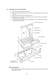
... s Reassembling Notes • When installing the spring plate B and separation rubber, align their cutouts with the FPC key. IV - 7 Document pressure bar ADF parts Spring plate A Separation rubber Spring plate B Nip-related parts Panel rear cover 15 "X" pawls Control panel (placed upside down . (2) Remove the document pressure bar, ADF... parts, and nip-related parts from the panel rear cover. (3) Remove the two screws from the panel rear cover. (4) While lifting up the front edge of ...
... s Reassembling Notes • When installing the spring plate B and separation rubber, align their cutouts with the FPC key. IV - 7 Document pressure bar ADF parts Spring plate A Separation rubber Spring plate B Nip-related parts Panel rear cover 15 "X" pawls Control panel (placed upside down . (2) Remove the document pressure bar, ADF... parts, and nip-related parts from the panel rear cover. (3) Remove the two screws from the panel rear cover. (4) While lifting up the front edge of ...

Service Manual
Page 60
... main cover: • Cover glass. Remove them while slightly pulling up towards you. • Ejection leaf springs. 1.8 Scanner Frame ASSY (1) You can remove the following parts from the top of the scanner frame ASSY without taking out the ASSY from the document sensor PCB.
... main cover: • Cover glass. Remove them while slightly pulling up towards you. • Ejection leaf springs. 1.8 Scanner Frame ASSY (1) You can remove the following parts from the top of the scanner frame ASSY without taking out the ASSY from the document sensor PCB.

Service Manual
Page 67
... low-voltage power supply PCB. IV - 17 NCU PCB (beneath the main PCB) Main cover (placed upside down ) s Reassembling Notes • When reassembling the above parts, make sure that the above harnesses are routed through the clamps provided on the main cover as illustrated in Section 1.23.
... low-voltage power supply PCB. IV - 17 NCU PCB (beneath the main PCB) Main cover (placed upside down ) s Reassembling Notes • When reassembling the above parts, make sure that the above harnesses are routed through the clamps provided on the main cover as illustrated in Section 1.23.

Service Manual
Page 68
... power supply PCB, check the high-voltage contacts for any toner particles, paper dust or dirt, and clean them out. • When reassembling the above parts, make sure that the harnesses are routed on the main cover as illustrated in Section 1.23. • Once the fan motor film is placed upside...
... power supply PCB, check the high-voltage contacts for any toner particles, paper dust or dirt, and clean them out. • When reassembling the above parts, make sure that the harnesses are routed on the main cover as illustrated in Section 1.23. • Once the fan motor film is placed upside...

Service Manual
Page 74
... gear system Paper feed solenoid s Reassembling Notes • If the paper feed solenoid, solenoid lever, or clutch release lever has been removed, assemble the removed parts as shown above. (4) To replace the paper feed solenoid, solenoid lever or clutch release lever, remove the three screws and take off the motor bracket...
... gear system Paper feed solenoid s Reassembling Notes • If the paper feed solenoid, solenoid lever, or clutch release lever has been removed, assemble the removed parts as shown above. (4) To replace the paper feed solenoid, solenoid lever or clutch release lever, remove the three screws and take off the motor bracket...
Service Manual
Page 148
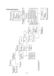
... • ADF and its related sections • Scanner motor and its harness • Document feed rollers and their related gears • Main PCB • ADF parts • Nip-related parts • Multi-purpose sheet feeder • Drum unit • Heat-fixing unit • Gear drive unit • Main PCB VI - 14
... • ADF and its related sections • Scanner motor and its harness • Document feed rollers and their related gears • Main PCB • ADF parts • Nip-related parts • Multi-purpose sheet feeder • Drum unit • Heat-fixing unit • Gear drive unit • Main PCB VI - 14

