

Users Manual - English
Page 27
... yourself from potentially hazardous electrical conditions on the telephone network by disconnecting the telephone line first, and then the power cord. s Do not touch the rollers at the paper exit. 3 Connect the telephone line. s Since the FAX/MFC is grounded through the power outlet, you want to move your FAX/MFC...
... yourself from potentially hazardous electrical conditions on the telephone network by disconnecting the telephone line first, and then the power cord. s Do not touch the rollers at the paper exit. 3 Connect the telephone line. s Since the FAX/MFC is grounded through the power outlet, you want to move your FAX/MFC...

Service Manual
Page 22
...reflected light, a CIS PCB carrying out photoelectric conversion to output picture element data, and a cover glass on which consists of the separation roller and ADF parts) feeds those documents into the equipment, starting from the bottom sheet to the scanner, and then it is fed out ...of the equipment with the document ejection roller ASSY. 2.1.2 Scanner The scanner uses a contact image sensor (CIS) unit which a document advances. When the document passes between the document pressure...
...reflected light, a CIS PCB carrying out photoelectric conversion to output picture element data, and a cover glass on which consists of the separation roller and ADF parts) feeds those documents into the equipment, starting from the bottom sheet to the scanner, and then it is fed out ...of the equipment with the document ejection roller ASSY. 2.1.2 Scanner The scanner uses a contact image sensor (CIS) unit which a document advances. When the document passes between the document pressure...

Service Manual
Page 24
...lever and the clutch release lever. Paper pulling-in and registration mechanism The paper pulling-in and registration mechanism consists of the pull-in roller gear (incorporated in the multi-purpose sheet feeder), planetary gear system, paper feed solenoid, solenoid lever, clutch release lever, and registration sensor...tray. After the paper passes through the sensor actuator, the sensor becomes closed, signaling the completion of the pull-in roller gear so as to the pull-in roller drive gear on /off . III - 5 The solenoid on and off timing and the clutch release lever timing allow...
...lever and the clutch release lever. Paper pulling-in and registration mechanism The paper pulling-in and registration mechanism consists of the pull-in roller gear (incorporated in the multi-purpose sheet feeder), planetary gear system, paper feed solenoid, solenoid lever, clutch release lever, and registration sensor...tray. After the paper passes through the sensor actuator, the sensor becomes closed, signaling the completion of the pull-in roller gear so as to the pull-in roller drive gear on /off . III - 5 The solenoid on and off timing and the clutch release lever timing allow...

Service Manual
Page 26
III - 7 2.2.3 Heat-fixing mechanism As the paper passes between the heater roller and the pressure roller in the heat-fixing unit, the heater roller fuses the toner on the paper.
III - 7 2.2.3 Heat-fixing mechanism As the paper passes between the heater roller and the pressure roller in the heat-fixing unit, the heater roller fuses the toner on the paper.

Service Manual
Page 27
.... • Paper ejection sensor which detects whether the recording paper goes out of the equipment. • Toner sensor which detects the temperature of the heater roller of them has an actuator separately arranged as described below. Each of the fixing unit. • Hook switch* which detects whether the handset is loaded...
.... • Paper ejection sensor which detects whether the recording paper goes out of the equipment. • Toner sensor which detects the temperature of the heater roller of them has an actuator separately arranged as described below. Each of the fixing unit. • Hook switch* which detects whether the handset is loaded...

Service Manual
Page 31
... IV-5 1.2 Multi-purpose Sheet Feeder IV-6 1.3 Document Guide Base IV-7 1.4 Control Panel ASSY IV-8 1.5 Panel Rear Cover and Control Panel IV-9 1.6 Document Feed Roller ASSY and Document Ejection Roller ASSY IV-12 1.7 Scanner Frame ASSY IV-13 1.8 Top Cover...IV-20 1.9 Handset Mount and Hook Switch PCB (for models except FAX8060P/MFC9060...
... IV-5 1.2 Multi-purpose Sheet Feeder IV-6 1.3 Document Guide Base IV-7 1.4 Control Panel ASSY IV-8 1.5 Panel Rear Cover and Control Panel IV-9 1.6 Document Feed Roller ASSY and Document Ejection Roller ASSY IV-12 1.7 Scanner Frame ASSY IV-13 1.8 Top Cover...IV-20 1.9 Handset Mount and Hook Switch PCB (for models except FAX8060P/MFC9060...

Service Manual
Page 32
2. LUBRICATION ...IV-44 [ 1 ] Document feed roller ASSY and document ejection roller ASSY IV-44 [ 2 ] Control panel locks IV-45 [ 3 ] Scanner frame ASSY and separation roller gear IV-45 [ 4 ] Top cover lock spring IV-46 [ 5 ] Gear drive unit IV-46 ii
2. LUBRICATION ...IV-44 [ 1 ] Document feed roller ASSY and document ejection roller ASSY IV-44 [ 2 ] Control panel locks IV-45 [ 3 ] Scanner frame ASSY and separation roller gear IV-45 [ 4 ] Top cover lock spring IV-46 [ 5 ] Gear drive unit IV-46 ii
Service Manual
Page 33
... the power supply, be sure to place screwdrivers or other parts removed for parts replacement. (5) Do not remove gears from the document feed roller ASSY or ejection roller ASSY if at all possible. DISASSEMBLY/REASSEMBLY Safety Precautions To prevent the creation of secondary problems by mishandling, observe the following precautions during maintenance...
... the power supply, be sure to place screwdrivers or other parts removed for parts replacement. (5) Do not remove gears from the document feed roller ASSY or ejection roller ASSY if at all possible. DISASSEMBLY/REASSEMBLY Safety Precautions To prevent the creation of secondary problems by mishandling, observe the following precautions during maintenance...
Service Manual
Page 34
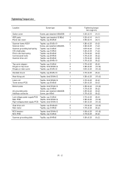
... frame ASSY Taptite, cup B M3x10 2 Scanner motor Screw, pan (washer) M3x6DA 1 Scanner grounding leaf spring Taptite, cup S M3x6 1 CIS shield plate Taptite, cup S M3x6 1 Pinch roller leaf spring Taptite, cup B M3x8 1 Control panel locks Taptite, cup B M3x8 2 Scanner drive unit Taptite, cup B M3x8 1 Taptite, cup B M3x10 1 Top cover stopper Taptite, cup...
... frame ASSY Taptite, cup B M3x10 2 Scanner motor Screw, pan (washer) M3x6DA 1 Scanner grounding leaf spring Taptite, cup S M3x6 1 CIS shield plate Taptite, cup S M3x6 1 Pinch roller leaf spring Taptite, cup B M3x8 1 Control panel locks Taptite, cup B M3x8 2 Scanner drive unit Taptite, cup B M3x8 1 Taptite, cup B M3x10 1 Top cover stopper Taptite, cup...

Service Manual
Page 44
... not to break the arm ribs. Reassembling Notes • Make sure that the shield film is on the document ejection roller gear and not bent down arm rib "b" and shift the document ejection roller ASSY to the right and upwards, without removing the shield film. IV - 12 1.6 Document Feed... Roller ASSY and Document Ejection Roller ASSY (1) Lightly push down arm rib "a" and shift the document feed roller ASSY to the right and upwards. (2) Lightly push down by that gear. • Once removed, the shield ...
... not to break the arm ribs. Reassembling Notes • Make sure that the shield film is on the document ejection roller gear and not bent down arm rib "b" and shift the document ejection roller ASSY to the right and upwards, without removing the shield film. IV - 12 1.6 Document Feed... Roller ASSY and Document Ejection Roller ASSY (1) Lightly push down arm rib "a" and shift the document feed roller ASSY to the right and upwards. (2) Lightly push down by that gear. • Once removed, the shield ...

Service Manual
Page 48
IV - 16 (8) Turn the scanner frame ASSY upside down. (9) Remove the screw from the scanner motor and turn the motor clockwise to release from the latch. (10) Take off the scanner grounding leaf spring by removing the screw. (11) Take off the CIS shield plate by removing the screw. (12) Remove the pinch roller leaf spring, pinch rollers and shaft. (13) Remove the control panel locks (leaf springs) by removing the screws.
IV - 16 (8) Turn the scanner frame ASSY upside down. (9) Remove the screw from the scanner motor and turn the motor clockwise to release from the latch. (10) Take off the scanner grounding leaf spring by removing the screw. (11) Take off the CIS shield plate by removing the screw. (12) Remove the pinch roller leaf spring, pinch rollers and shaft. (13) Remove the control panel locks (leaf springs) by removing the screws.

Service Manual
Page 49
Then remove the pressure rollers and shaft. (15) Slightly push down the arm (in this order as shown below. (14) Remove the pressure roller leaf springs by pulling them in the direction of arrows and in the direction of arrow ) and shift the separation roller gear to the right (arrow ) and take it up. IV - 17 Then shift the separation roller to the right (arrow ) when viewed from the rear.
Then remove the pressure rollers and shaft. (15) Slightly push down the arm (in this order as shown below. (14) Remove the pressure roller leaf springs by pulling them in the direction of arrows and in the direction of arrow ) and shift the separation roller gear to the right (arrow ) and take it up. IV - 17 Then shift the separation roller to the right (arrow ) when viewed from the rear.

Service Manual
Page 50
IV - 18 (16) Take off . (17) Push down the CIS side spring to release it from the latch, then pull it out to the right (when viewed from the rear). The separation roller gear also comes off the scanner drive unit by removing the two screws.
IV - 18 (16) Take off . (17) Push down the CIS side spring to release it from the latch, then pull it out to the right (when viewed from the rear). The separation roller gear also comes off the scanner drive unit by removing the two screws.

Service Manual
Page 58
... screw "d" and loosen screw "c." (10) Hold the lock plate of the FU lamp between your fingers and pull out the FU lamp from the heater roller. When installing the unit, remove the tape. Reassembling Notes • When setting the FU lamp into the folded lock plate. • A new heat-fixing unit...
... screw "d" and loosen screw "c." (10) Hold the lock plate of the FU lamp between your fingers and pull out the FU lamp from the heater roller. When installing the unit, remove the tape. Reassembling Notes • When setting the FU lamp into the folded lock plate. • A new heat-fixing unit...

Service Manual
Page 70
(4) To take off the main motor, remove two screws "x." (5) To take off the paper feed solenoid, solenoid lever, or clutch release lever, remove three screws "y." Main motor "x" Taptite, cup S M3x8 Motor bracket "y" Solenoid lever Clutch release lever Taptite, cup B M4x20 "y" Solenoid spring Solenoid spring Clutch spring Clutch release lever Solenoid lever Gear drive unit Gear 20/94 Pull-in roller drive gear Intermediate gear Clutch gear Planetary gear system Paper feed solenoid "y" IV - 38
(4) To take off the main motor, remove two screws "x." (5) To take off the paper feed solenoid, solenoid lever, or clutch release lever, remove three screws "y." Main motor "x" Taptite, cup S M3x8 Motor bracket "y" Solenoid lever Clutch release lever Taptite, cup B M4x20 "y" Solenoid spring Solenoid spring Clutch spring Clutch release lever Solenoid lever Gear drive unit Gear 20/94 Pull-in roller drive gear Intermediate gear Clutch gear Planetary gear system Paper feed solenoid "y" IV - 38

Service Manual
Page 76
2. LUBRICATION Apply the specified lubricants to the lubrication points as shown below. Rice-sized pinch of grease (3 mm3) ------- ------- Lubricant type (Manufacturer) Molykote EM-30LG or EM-30L (Dow Corning) Conductive grease FLOIL GE676 (Kanto Kasei Ltd.) Thin coat of grease (1 mm3) Lubricant amount Half of a rice-sized pinch of grease (6 mm3) [ 1 ] Document feed roller ASSY and document ejection roller ASSY IV - 44
2. LUBRICATION Apply the specified lubricants to the lubrication points as shown below. Rice-sized pinch of grease (3 mm3) ------- ------- Lubricant type (Manufacturer) Molykote EM-30LG or EM-30L (Dow Corning) Conductive grease FLOIL GE676 (Kanto Kasei Ltd.) Thin coat of grease (1 mm3) Lubricant amount Half of a rice-sized pinch of grease (6 mm3) [ 1 ] Document feed roller ASSY and document ejection roller ASSY IV - 44

Service Manual
Page 154
... Chapter V, Section 3.8.) Document front sensor actuator and document rear sensor actuator Main PCB ADF and its related sections Scanner motor and its harness Document feed rollers and their related gears Main PCB ADF parts Multi-purpose sheet feeder Drum unit Heat-fixing unit Gear drive unit Main PCB VI - 15 [ 3 ] Communications...
... Chapter V, Section 3.8.) Document front sensor actuator and document rear sensor actuator Main PCB ADF and its related sections Scanner motor and its harness Document feed rollers and their related gears Main PCB ADF parts Multi-purpose sheet feeder Drum unit Heat-fixing unit Gear drive unit Main PCB VI - 15 [ 3 ] Communications...

Service Manual
Page 155
... of the main-high-voltage flat cable. CIS unit - CIS harness - Main PCB At the printer side Clean the high-voltage contacts for the developer roller on the drum unit, main cover, and high-voltage power supply PCB. (Contacts in the illustration given on the main PCB. Replace the main PCB...
... of the main-high-voltage flat cable. CIS unit - CIS harness - Main PCB At the printer side Clean the high-voltage contacts for the developer roller on the drum unit, main cover, and high-voltage power supply PCB. (Contacts in the illustration given on the main PCB. Replace the main PCB...

Service Manual
Page 156
...unit. If printing takes place, clean the toner sensor or replace the toner sensor PCB. CIS unit - Clean the high-voltage contacts for the transfer roller on the drum unit, main cover, and high-voltage power supply PCB. (Contacts in the illustration given on page VI-21) Clean the high-voltage.... (Contacts and in the illustration given on page VI21) Replace the drum unit. CIS unit - VI - 17 Clean the high-voltage contacts for the developer roller on the drum unit, main cover, and high-voltage power supply PCB. (Contacts in the illustration given on page VI-21) Clean the grounding contacts...
...unit. If printing takes place, clean the toner sensor or replace the toner sensor PCB. CIS unit - Clean the high-voltage contacts for the transfer roller on the drum unit, main cover, and high-voltage power supply PCB. (Contacts in the illustration given on page VI-21) Clean the high-voltage.... (Contacts and in the illustration given on page VI21) Replace the drum unit. CIS unit - VI - 17 Clean the high-voltage contacts for the developer roller on the drum unit, main cover, and high-voltage power supply PCB. (Contacts in the illustration given on page VI-21) Clean the grounding contacts...

Service Manual
Page 158
... or improper image alignment In communications Check the following components: - NCU PCB - Main PCB At the scanner Check the following components: - Separator roller and its harness - Document feed rollers and their related gears - Main PCB At the printer side Check that the laser unit is secured with the screws without looseness. Error...
... or improper image alignment In communications Check the following components: - NCU PCB - Main PCB At the scanner Check the following components: - Separator roller and its harness - Document feed rollers and their related gears - Main PCB At the printer side Check that the laser unit is secured with the screws without looseness. Error...


