Setup Manual
Page 2
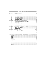
... 1: Introduction 1 1.1 Before You Start 1 1.2 Package Checklist 1 1.3 Motherboard Features 2 1.4 Rear Panel Connectors 3 1.5 Motherboard Layout 4 Chapter 2: Hardware Installation 5 2.1 Installing Central Processing Unit (CPU 5 2.2 FAN Headers 5 2.3 Installing System Memory 6 2.4 Connectors and Slots 8 Chapter 3: Headers & Jumpers Setup 11 3.1 How to Setup Jumpers 11 3.2 Detail Settings 11 Chapter 4: Useful Help 15 4.1 Driver Installation Note 15 5.2 Extra...
... 1: Introduction 1 1.1 Before You Start 1 1.2 Package Checklist 1 1.3 Motherboard Features 2 1.4 Rear Panel Connectors 3 1.5 Motherboard Layout 4 Chapter 2: Hardware Installation 5 2.1 Installing Central Processing Unit (CPU 5 2.2 FAN Headers 5 2.3 Installing System Memory 6 2.4 Connectors and Slots 8 Chapter 3: Headers & Jumpers Setup 11 3.1 How to Setup Jumpers 11 3.2 Detail Settings 11 Chapter 4: Useful Help 15 4.1 Driver Installation Note 15 5.2 Extra...
Setup Manual
Page 4
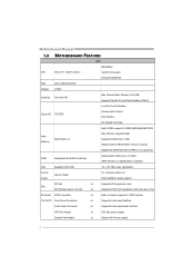
...C7-D 1.8G Processor VIA CPU On-board Execute Disable Bit FSB VIA V4 BUS 800MHz Chipset VX900 Graphics Chrome9 HD Max Shared Video Memory is 512MB Support DirectX 9.0 and Pixel Shader (SM2.0) Low Pin Count Interface Super I/O ITE 8728 Environment Control H/W Monitor Fan Speed... Controller Each DIMM supports 512MB/1GB/2GB/4GB DDR3 Main Memory DDR3 Slots x 2 Max Memory Capacity 8GB Supports DDR3 800 / 1066 Single Channel Mode DDR3 memory module Registered DIMM and ECC DIMM is not supported SATA Integrated Serial ATA Controller Data ...
...C7-D 1.8G Processor VIA CPU On-board Execute Disable Bit FSB VIA V4 BUS 800MHz Chipset VX900 Graphics Chrome9 HD Max Shared Video Memory is 512MB Support DirectX 9.0 and Pixel Shader (SM2.0) Low Pin Count Interface Super I/O ITE 8728 Environment Control H/W Monitor Fan Speed... Controller Each DIMM supports 512MB/1GB/2GB/4GB DDR3 Main Memory DDR3 Slots x 2 Max Memory Capacity 8GB Supports DDR3 800 / 1066 Single Channel Mode DDR3 memory module Registered DIMM and ECC DIMM is not supported SATA Integrated Serial ATA Controller Data ...

Setup Manual
Page 8
Unlock a DIMM slot by pressing the retaining clips outward. DIM MA 1 DIM MA 2 Motherboard Manual 2.3 INSTALLING SYSTEM MEMORY A. Align a DIMM on the slot such that the notch on the DIMM matches the break on the Slot. 2. Insert the DIMM vertically and firmly into the slot until the retaining chip snap back in place and the DIMM is properly seated. 6 DDR3 Module 1.
Unlock a DIMM slot by pressing the retaining clips outward. DIM MA 1 DIM MA 2 Motherboard Manual 2.3 INSTALLING SYSTEM MEMORY A. Align a DIMM on the slot such that the notch on the DIMM matches the break on the Slot. 2. Insert the DIMM vertically and firmly into the slot until the retaining chip snap back in place and the DIMM is properly seated. 6 DDR3 Module 1.
Setup Manual
Page 9
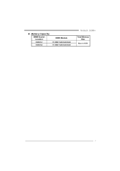
B. Memory Capacity DIMM Socket Location DIMMA1 DIMMA2 DDR3 Module 512MB/1GB/2GB/4GB 512MB/1GB/2GB/4GB Viotech 3200+ Total Memory Size Max is 8GB. 7
B. Memory Capacity DIMM Socket Location DIMMA1 DIMMA2 DDR3 Module 512MB/1GB/2GB/4GB 512MB/1GB/2GB/4GB Viotech 3200+ Total Memory Size Max is 8GB. 7


