Setup Manual
Page 6
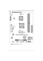
Motherboard Manual 1.5 MOTHERBOARD LAYOUT KBMS1 ATX PW R 2 VGA1 C P U_FA N1 VIA C7-D 1.8G CP U 1 D I MM A 1 D I MM A 2 USB3 J U SB V 2 R J 45U S B1 A U DI O1 LAN VIA VX900 SATA2 F_U S B2 JUSBV1 SATA1 F_USB1 PEX16_1 ATX PW R 1 Codec BAT1 PCI1 Super I/O BIOS J C MOS 1 F_AUDIO1 J_COM1 J_PRINT1 Note: ■ represents the 1st pin. SYS_FAN1 PANEL1 4
Motherboard Manual 1.5 MOTHERBOARD LAYOUT KBMS1 ATX PW R 2 VGA1 C P U_FA N1 VIA C7-D 1.8G CP U 1 D I MM A 1 D I MM A 2 USB3 J U SB V 2 R J 45U S B1 A U DI O1 LAN VIA VX900 SATA2 F_U S B2 JUSBV1 SATA1 F_USB1 PEX16_1 ATX PW R 1 Codec BAT1 PCI1 Super I/O BIOS J C MOS 1 F_AUDIO1 J_COM1 J_PRINT1 Note: ■ represents the 1st pin. SYS_FAN1 PANEL1 4
Setup Manual
Page 15
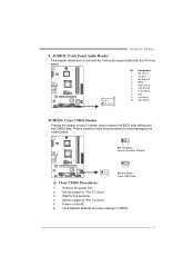
Viotech 3200+ F_AUDIO1: Front Panel Audio Header This header allows user to connect the front audio output cable with the PC front panel. 2 10 Pin Assignment 1 Mic ... in CMOS. 13 Wait for five seconds. 4. Remove AC power line. 2. Set the jumper to "Pin 1-2 close ". 3. Please carefully follow the procedures to restore the BIOS safe setting and the CMOS data. Set the jumper to "Pin 2-3 close ". 5. Power on pin2-3 allows user to avoid damaging the motherboard. 13 Pin 1-2 Close...
Viotech 3200+ F_AUDIO1: Front Panel Audio Header This header allows user to connect the front audio output cable with the PC front panel. 2 10 Pin Assignment 1 Mic ... in CMOS. 13 Wait for five seconds. 4. Remove AC power line. 2. Set the jumper to "Pin 1-2 close ". 3. Please carefully follow the procedures to restore the BIOS safe setting and the CMOS data. Set the jumper to "Pin 2-3 close ". 5. Power on pin2-3 allows user to avoid damaging the motherboard. 13 Pin 1-2 Close...

