
U8668 Grand user's manual
Page 2
...Connectors 4-1. Front Panel Connector: JPANEL1 4-2. Floppy Disk Connector: FDD1 4-5. Clear CMOS Jumper: JCMOS1 4-7. Notice Mainboard Features 1. Package Contents 2. Mainboard Configuration 2-1. System Fan Header: JSFAN1 4. Wake On LAN Header: JWOL1 4-6. Front USB Header: JUSB3 4-8. Hardware 1-2. Component Index 3. Front USB Header: JUSB4 4-9. 5V / 5VSB Selection for KB: JKBV1 ATX 20-pin Power Connector: JATXPWR1 4-3. CPU Socket 478 Configuration Steps: 3-2. Hard Disk Connectors: IDE1/IDE2 4-4. Features Introduction 1-1. CPU Configuration 3-1. BIOS & Software...
...Connectors 4-1. Front Panel Connector: JPANEL1 4-2. Floppy Disk Connector: FDD1 4-5. Clear CMOS Jumper: JCMOS1 4-7. Notice Mainboard Features 1. Package Contents 2. Mainboard Configuration 2-1. System Fan Header: JSFAN1 4. Wake On LAN Header: JWOL1 4-6. Front USB Header: JUSB3 4-8. Hardware 1-2. Component Index 3. Front USB Header: JUSB4 4-9. 5V / 5VSB Selection for KB: JKBV1 ATX 20-pin Power Connector: JATXPWR1 4-3. CPU Socket 478 Configuration Steps: 3-2. Hard Disk Connectors: IDE1/IDE2 4-4. Features Introduction 1-1. CPU Configuration 3-1. BIOS & Software...

U8668 Grand user's manual
Page 3
ATX 12V Power Connector: JATXPWR2 4-11. 5V / 5VSB Selection for USB: JUSBV3 4-12. 5V / 5VSB Selection for USB: JUSBV4 5. USB & LAN Port Connectors: JUSBLAN1 6-3. Game (Joystick/MIDI) Port Connector: JAUD_GAME 6-5. Peripheral Port Features 6-1. Serial and Parallel Interface Ports 6-4. Audio Port Connectors: JSPKR1/JLIN1/JMIC1 6-6. DDR SDRAM 5-2 SDRAM 5-3. PS/2 Mouse / Keyboard Connector: JKBMS1 6-2. Audio Subsystem RAM Module Configuration 5-1. 4-10. How to install DDR/SDRAM DIMM Module 6.
ATX 12V Power Connector: JATXPWR2 4-11. 5V / 5VSB Selection for USB: JUSBV3 4-12. 5V / 5VSB Selection for USB: JUSBV4 5. USB & LAN Port Connectors: JUSBLAN1 6-3. Game (Joystick/MIDI) Port Connector: JAUD_GAME 6-5. Peripheral Port Features 6-1. Serial and Parallel Interface Ports 6-4. Audio Port Connectors: JSPKR1/JLIN1/JMIC1 6-6. DDR SDRAM 5-2 SDRAM 5-3. PS/2 Mouse / Keyboard Connector: JKBMS1 6-2. Audio Subsystem RAM Module Configuration 5-1. 4-10. How to install DDR/SDRAM DIMM Module 6.
U8668 Grand user's manual
Page 5
... 512Mb technologies for high-end workstations and servers. 1.Runing at 400/ 533 MHz Front Side Bus frequency. 2.Supports up to 2.8 GHz CPU core speeds. 3.The 33MHz 32 bit PCI 2.2 compliant. 4.The 66MHz AGP 2.0 compliant interface supports 1x, 2x and 4x data transfer mode. Features Introduction 1-1. Chipset - Mainboard Features 1. VIA VT8751A (P4M266A)/ VT8235. Hardware 1.Provides Socket-478. 2.Supports the Intel Pentium ® processor providing the new generation power for...
... 512Mb technologies for high-end workstations and servers. 1.Runing at 400/ 533 MHz Front Side Bus frequency. 2.Supports up to 2.8 GHz CPU core speeds. 3.The 33MHz 32 bit PCI 2.2 compliant. 4.The 66MHz AGP 2.0 compliant interface supports 1x, 2x and 4x data transfer mode. Features Introduction 1-1. Chipset - Mainboard Features 1. VIA VT8751A (P4M266A)/ VT8235. Hardware 1.Provides Socket-478. 2.Supports the Intel Pentium ® processor providing the new generation power for...
U8668 Grand user's manual
Page 6
...-bit PCI bus slots 1.Dual Speed - 100/ 10 Mbps. 2.Half and Full Duplex. 3.MII Interface to Ethernet Controller. 4.Optional Repeater Interface. 5.Auto Negotiation: 10/ 100, Full/ Half Duplex. 6.Meet All Applicable IEEE 802.3, 10Base-Tx Standards. 7.Baseline Wander Correction. 1.Supports flash memory functionality. 2.Supports ESCD functionality. 1.250 MHz RAMDAC on chip with Gamma Correction. 2.Horizontal / Vertical Sync outputs compliant with a memory controller providing shadow RAM and support for ROM BIOS. 1.Supports Award BIOS...
...-bit PCI bus slots 1.Dual Speed - 100/ 10 Mbps. 2.Half and Full Duplex. 3.MII Interface to Ethernet Controller. 4.Optional Repeater Interface. 5.Auto Negotiation: 10/ 100, Full/ Half Duplex. 6.Meet All Applicable IEEE 802.3, 10Base-Tx Standards. 7.Baseline Wander Correction. 1.Supports flash memory functionality. 2.Supports ESCD functionality. 1.250 MHz RAMDAC on chip with Gamma Correction. 2.Horizontal / Vertical Sync outputs compliant with a memory controller providing shadow RAM and support for ROM BIOS. 1.Supports Award BIOS...
U8668 Grand user's manual
Page 7
... rate. 7. Optimized Shared Memory Architecture (SMA). 2. 16 / 32 MB frame buffer using system memory. 3. Microsoft Direct X texture compression. 9. Vertex and table fog. 10. 16 or 24-bit Z-buffering. 11. Floating-point triangle setup engine. 4. MPEG-2 video textures. 9. Reflection mapping, texture morphing, shadows, procedural textures and atmospheric effects. 1.Supports four IDE hard disk drives. 2.Supports PIO Mode 4, Master Mode, and high performance hard disk drives. 3.Supports disk transfer rates up to...
... rate. 7. Optimized Shared Memory Architecture (SMA). 2. 16 / 32 MB frame buffer using system memory. 3. Microsoft Direct X texture compression. 9. Vertex and table fog. 10. 16 or 24-bit Z-buffering. 11. Floating-point triangle setup engine. 4. MPEG-2 video textures. 9. Reflection mapping, texture morphing, shadows, procedural textures and atmospheric effects. 1.Supports four IDE hard disk drives. 2.Supports PIO Mode 4, Master Mode, and high performance hard disk drives. 3.Supports disk transfer rates up to...
U8668 Grand user's manual
Page 8
... panel Universal Serial Bus (USB2.0) Ports and four front panel Universal Serial Bus (USB2.0) Ports. 1.Monitors CPU Fan Speed. 2.Monitors System Voltage. 3.Monitors System Fan Speed. 24.5cm x 24.5cm (WxL) Extended Capabilities Port (ECP). Normal 2.Supports one serial port, 16550 UART. 3.Supports Infrared Data Transmission using IrDA. 4.Supports PS/2 mouse and PS/2 keyboard. 5.Supports 360KB, 720KB, 1.2MB, 1.44MB, and 2.88MB floppy disk drives. Enhanced Parallel Port (EPP). Master Modes. 5.Supports IDE interface with CD-ROM. 6.Supports high capacity hard disk drives. 7.Supports LBA mode...
... panel Universal Serial Bus (USB2.0) Ports and four front panel Universal Serial Bus (USB2.0) Ports. 1.Monitors CPU Fan Speed. 2.Monitors System Voltage. 3.Monitors System Fan Speed. 24.5cm x 24.5cm (WxL) Extended Capabilities Port (ECP). Normal 2.Supports one serial port, 16550 UART. 3.Supports Infrared Data Transmission using IrDA. 4.Supports PS/2 mouse and PS/2 keyboard. 5.Supports 360KB, 720KB, 1.2MB, 1.44MB, and 2.88MB floppy disk drives. Enhanced Parallel Port (EPP). Master Modes. 5.Supports IDE interface with CD-ROM. 6.Supports high capacity hard disk drives. 7.Supports LBA mode...
U8668 Grand user's manual
Page 9
Package Contents 1.HDD Cable. 2.FDD Cable. 3.Flash Memory Writer for BIOS Update. 4.USB Cable (Optional). 5.Rear I/O Panel for MS-DOS, Windows NT, Windows 2000, Windows ME, Windows XP, Novell, LINUX, and SCO UNIX etc. 1-3. 1-2. Offers the highest performance for MATX Case (Optional). 6.Fully Setup Driver CD. BIOS & Software 1.Award legal BIOS. 2.Supports APM1.2. 3.Supports USB Function. 4.Supports ACPI.
Package Contents 1.HDD Cable. 2.FDD Cable. 3.Flash Memory Writer for BIOS Update. 4.USB Cable (Optional). 5.Rear I/O Panel for MS-DOS, Windows NT, Windows 2000, Windows ME, Windows XP, Novell, LINUX, and SCO UNIX etc. 1-3. 1-2. Offers the highest performance for MATX Case (Optional). 6.Fully Setup Driver CD. BIOS & Software 1.Award legal BIOS. 2.Supports APM1.2. 3.Supports USB Function. 4.Supports ACPI.
U8668 Grand user's manual
Page 10
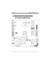
Layout of U8668 Grand 2. Mainboard Configuration 2-1.
Layout of U8668 Grand 2. Mainboard Configuration 2-1.
U8668 Grand user's manual
Page 12
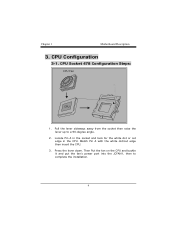
Locate Pin A in the CPU. Then Put the fan on the CPU and buckle it and put the fan's power port into the JCFAN1, then to a 90-degree angle. 2. CPU Socket 478 Configuration Steps: CPU Fan CPU 1. Press the lever down. Pull the lever sideways away from the socket then raise the lever up to complete the installation. Match Pin A with the white dot/cut edge in the socket and look for the white dot or cut edge then insert the CPU. 3. CPU Configuration 3-1. 3.
Locate Pin A in the CPU. Then Put the fan on the CPU and buckle it and put the fan's power port into the JCFAN1, then to a 90-degree angle. 2. CPU Socket 478 Configuration Steps: CPU Fan CPU 1. Press the lever down. Pull the lever sideways away from the socket then raise the lever up to complete the installation. Match Pin A with the white dot/cut edge in the socket and look for the white dot or cut edge then insert the CPU. 3. CPU Configuration 3-1. 3.
U8668 Grand user's manual
Page 16
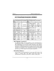
... POST (Power On Self Test). An offboard speaker can be installed on 15 Reset Control Button 16 Ground Button 17 NA 18 KEY 19 NA IrDA 20 KEY IrDA 21 VCC5 Connector 22 Ground Connector 23 IRTX 24 IRRX SPK (Speaker Connector) An offboard speaker can be attached to the motherboard at the front panel connector. No. 1 +5V 2 Sleep Control Sleep 3 NA Speaker 4 Ground Button 5 NA Connector 6 NA NA 7 Speaker 8 Power LED (+) 9 HDD LED (+) Hard Drive 10 Power LED (+) POWER 11 HDD LED (-) LED 12 Power LED (-) LED 13 Ground Reset...
... POST (Power On Self Test). An offboard speaker can be installed on 15 Reset Control Button 16 Ground Button 17 NA 18 KEY 19 NA IrDA 20 KEY IrDA 21 VCC5 Connector 22 Ground Connector 23 IRTX 24 IRRX SPK (Speaker Connector) An offboard speaker can be attached to the motherboard at the front panel connector. No. 1 +5V 2 Sleep Control Sleep 3 NA Speaker 4 Ground Button 5 NA Connector 6 NA NA 7 Speaker 8 Power LED (+) 9 HDD LED (+) Hard Drive 10 Power LED (+) POWER 11 HDD LED (-) LED 12 Power LED (-) LED 13 Ground Reset...
U8668 Grand user's manual
Page 17
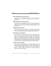
... Power Button pin to ground for at least 50 ms to signal the power supply to switch on the system board). ON/OFF (Power Button) This connector can be loaded. HLED (Hard Drive LED Connector) This connector can be enabled in use. Depressing the button will recognize another on . The LED will flicker during disk activity. To configure this connector. The switch must be attached to an LED on the front panel of a computer case. APM (Advanced Power...
... Power Button pin to ground for at least 50 ms to signal the power supply to switch on the system board). ON/OFF (Power Button) This connector can be loaded. HLED (Hard Drive LED Connector) This connector can be enabled in use. Depressing the button will recognize another on . The LED will flicker during disk activity. To configure this connector. The switch must be attached to an LED on the front panel of a computer case. APM (Advanced Power...
U8668 Grand user's manual
Page 18
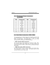
Hard Disk Connectors: IDE1/IDE2 This mainboard has a 32-bit Enhanced PCI IDE Controller that provides PIO Mode 0~4, Bus Master, and Ultra DMA / 33, Ultra DMA / 66,Ultra DMA / 100 functionality. 4-2. You must be connected to Slave mode by setting the jumper accordingly. • IDE2 (Secondary IDE Connector) The IDE2 controller can connect a Master and a Slave drive. The configuration is similar to slave mode. ATX 20-pin Power Connector: JATXPWR1 PIN 1 2 3 4 5 6 7 8 9 10 Assignment +3.3V +3.3V Ground +5V...
Hard Disk Connectors: IDE1/IDE2 This mainboard has a 32-bit Enhanced PCI IDE Controller that provides PIO Mode 0~4, Bus Master, and Ultra DMA / 33, Ultra DMA / 66,Ultra DMA / 100 functionality. 4-2. You must be connected to Slave mode by setting the jumper accordingly. • IDE2 (Secondary IDE Connector) The IDE2 controller can connect a Master and a Slave drive. The configuration is similar to slave mode. ATX 20-pin Power Connector: JATXPWR1 PIN 1 2 3 4 5 6 7 8 9 10 Assignment +3.3V +3.3V Ground +5V...
U8668 Grand user's manual
Page 19
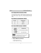
4-4. Wake On LAN Header: JWOL1 Pin No. 1 2 3 Assignment +5V SB Ground Wake up 4-6. Floppy Disk Connector: FDD1 The motherboard provides a standard floppy disk connector (FDC) that supports 360K, 720K, 1.2M, 1.44M and 2.88M floppy disk types. Make JCMOS1 (2-3) closed. Remove AC power line. 2. This connector supports the provided floppy drive ribbon cables. 4-5. Clear CMOS Jumper: JCMOS1 JCMOS1 1 3 1-2 Closed 1 3 2-3 Closed Assignment Normal Operation (default) Clear CMOS Data Clear CMOS Procedures: 1.
4-4. Wake On LAN Header: JWOL1 Pin No. 1 2 3 Assignment +5V SB Ground Wake up 4-6. Floppy Disk Connector: FDD1 The motherboard provides a standard floppy disk connector (FDC) that supports 360K, 720K, 1.2M, 1.44M and 2.88M floppy disk types. Make JCMOS1 (2-3) closed. Remove AC power line. 2. This connector supports the provided floppy drive ribbon cables. 4-5. Clear CMOS Jumper: JCMOS1 JCMOS1 1 3 1-2 Closed 1 3 2-3 Closed Assignment Normal Operation (default) Clear CMOS Data Clear CMOS Procedures: 1.

U8668 Grand user's manual
Page 20
3. Reset your desired password or clear the CMOS data. 4-7. Front USB Header: JUSB3 (JUSB3) Pin 1 3 5 7 9 Assignment +5V(fused) USBP2USBP2+ Ground KEY Pin Assignment 2 +5V(fused) 4 USBP3- 6 USBP3+ 8 Ground 10 NC 4-8. Wait for KB: JKBV1 JKBV1 Assignment Let AC power on. 6. Front USB Header: JUSB4 (JUSB4) Pin 1 3 5 7 9 Assignment +5V(fused) USBP2USBP2+ Ground KEY Pin Assignment 2 +5V(fused) 4 USBP3- 6 USBP3+ 8 Ground 10 NC 4-9. 5V / 5VSB Selection for five seconds. 4. Make JCMOS1 (1-2) closed. 5.
3. Reset your desired password or clear the CMOS data. 4-7. Front USB Header: JUSB3 (JUSB3) Pin 1 3 5 7 9 Assignment +5V(fused) USBP2USBP2+ Ground KEY Pin Assignment 2 +5V(fused) 4 USBP3- 6 USBP3+ 8 Ground 10 NC 4-8. Wait for KB: JKBV1 JKBV1 Assignment Let AC power on. 6. Front USB Header: JUSB4 (JUSB4) Pin 1 3 5 7 9 Assignment +5V(fused) USBP2USBP2+ Ground KEY Pin Assignment 2 +5V(fused) 4 USBP3- 6 USBP3+ 8 Ground 10 NC 4-9. 5V / 5VSB Selection for five seconds. 4. Make JCMOS1 (1-2) closed. 5.

U8668 Grand user's manual
Page 22
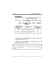
DRAM Type: 128MB/ 256MB/ 512MB/ 1GB DIMM Module (184 pin) Total Memory Size with unbuffer DIMMs 5. DDR SDRAM DRAM Access Time: 2.5V Unbuffered DDR SDRAM PC1600/ PC2100 Type required. RAM Module Configuration 5-1.
DRAM Type: 128MB/ 256MB/ 512MB/ 1GB DIMM Module (184 pin) Total Memory Size with unbuffer DIMMs 5. DDR SDRAM DRAM Access Time: 2.5V Unbuffered DDR SDRAM PC1600/ PC2100 Type required. RAM Module Configuration 5-1.
U8668 Grand user's manual
Page 23
It is forbidden to 3.3V. !For the above settings, you use one kind of memory simultaneously. DRAM Type: 128MB/ 256MB/ 512MB DIMM Module (168 pin) Total Memory Size with unbuffer DIMMs !When you use DDR SDRAM, the memory power will automatically set to 2.5V. !When you can only use SDRAM, the memory power will automatically set to insert both kind of memory on this motherboard. 5-2 SDRAM DRAM Access Time: 3.3V Unbuffered SDRAM PC100/ PC133 Type required. You must insert only DDR or SDRAM.
It is forbidden to 3.3V. !For the above settings, you use one kind of memory simultaneously. DRAM Type: 128MB/ 256MB/ 512MB DIMM Module (168 pin) Total Memory Size with unbuffer DIMMs !When you use DDR SDRAM, the memory power will automatically set to 2.5V. !When you can only use SDRAM, the memory power will automatically set to insert both kind of memory on this motherboard. 5-2 SDRAM DRAM Access Time: 3.3V Unbuffered SDRAM PC100/ PC133 Type required. You must insert only DDR or SDRAM.
U8668 Grand user's manual
Page 26
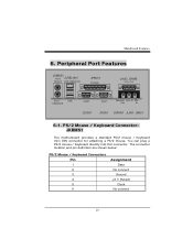
You can plug a PS/2 mouse / Keyboard directly into this connector. Peripheral Port Features JKBMS1 PS/2 JUSBLAN1 Mouse LAN (Optional) JPRNT1 Parallel JAUD_GAME PS/2 Keyboard USB COM1 VGA1 Speaker Line In Mic Out In JCOM1 JVGA1 JSPKR1 JLIN1 JMIC1 6-1. 6. The connector location and pin definition are shown below: PS/2 Mouse / Keyboard Connectors Pin 1 2 3 4 5 6 Assignment Data No connect Ground +5 V (fused) Clock No connect PS/2 Mouse / Keyboard Connector: JKBMS1 The motherboard provides a standard PS/2 mouse / Keyboard mini DIN connector for attaching a PS/2 mouse.
You can plug a PS/2 mouse / Keyboard directly into this connector. Peripheral Port Features JKBMS1 PS/2 JUSBLAN1 Mouse LAN (Optional) JPRNT1 Parallel JAUD_GAME PS/2 Keyboard USB COM1 VGA1 Speaker Line In Mic Out In JCOM1 JVGA1 JSPKR1 JLIN1 JMIC1 6-1. 6. The connector location and pin definition are shown below: PS/2 Mouse / Keyboard Connectors Pin 1 2 3 4 5 6 Assignment Data No connect Ground +5 V (fused) Clock No connect PS/2 Mouse / Keyboard Connector: JKBMS1 The motherboard provides a standard PS/2 mouse / Keyboard mini DIN connector for attaching a PS/2 mouse.
U8668 Grand user's manual
Page 28
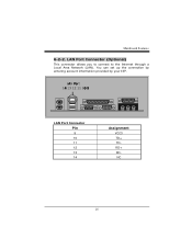
LAN Port Connector Pin 9 10 11 12 13 14 Assignment VCC3 TD+ TDRD+ RDNC LAN Port Connector (Optional) This connector allows you to connect to the Internet through a Local Area Network (LAN). You can set up the connection by entering account information provided by your ISP. 6-2-2.
LAN Port Connector Pin 9 10 11 12 13 14 Assignment VCC3 TD+ TDRD+ RDNC LAN Port Connector (Optional) This connector allows you to connect to the Internet through a Local Area Network (LAN). You can set up the connection by entering account information provided by your ISP. 6-2-2.
U8668 Grand user's manual
Page 29
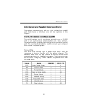
... equipped with the serial ports. Mice, printers, modems and other peripheral devices can be used when configuring certain software programs to as an RS-232 port or an asynchronous communication port. 6-3. This information can be necessary to connect your computer with the pinout diagram. Both types of the 25-pin connector. The following chart gives you the function of each pin on the 9-pin connector and some...
... equipped with the serial ports. Mice, printers, modems and other peripheral devices can be used when configuring certain software programs to as an RS-232 port or an asynchronous communication port. 6-3. This information can be necessary to connect your computer with the pinout diagram. Both types of the 25-pin connector. The following chart gives you the function of each pin on the 9-pin connector and some...
U8668 Grand BIOS setup guide
Page 8
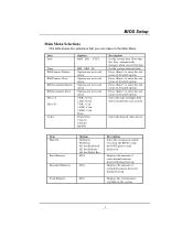
... enter the sub menu of detailed options. Press to enter the sub menu of detailed options. Displays the amount of floppy disk drive installed in the system. Options are in its sub menu. Options are in its sub menu. Select the type of conventional memory detected during boot up . Note that the 'Day' automatically changes when you want the BIOS to enter the sub menu of extended memory detected during boot up . Select the default video device...
... enter the sub menu of detailed options. Press to enter the sub menu of detailed options. Displays the amount of floppy disk drive installed in the system. Options are in its sub menu. Options are in its sub menu. Select the type of conventional memory detected during boot up . Note that the 'Day' automatically changes when you want the BIOS to enter the sub menu of extended memory detected during boot up . Select the default video device...


