
U8668 Grand user's manual
Page 6
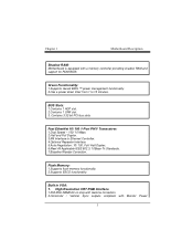
Motherboard is equipped with a memory controller providing shadow RAM and support for ROM BIOS. 1.Supports Award BIOS ™ power management functionality. 2.Has a power down timer from 1 ...
Motherboard is equipped with a memory controller providing shadow RAM and support for ROM BIOS. 1.Supports Award BIOS ™ power management functionality. 2.Has a power down timer from 1 ...
U8668 Grand user's manual
Page 16
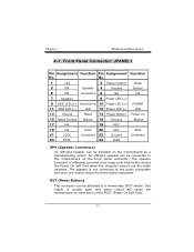
... 12 Power LED (-) LED 13 Ground Reset 14 Power Button Power-on the motherboard as a manufacturing option. The speaker is usually open and when closed will cause the motherboard to a momentary SPST switch. This switch is not connected to the motherboard at the front panel connector. The speaker (onboard or offboard) provides error...
... 12 Power LED (-) LED 13 Ground Reset 14 Power Button Power-on the motherboard as a manufacturing option. The speaker is usually open and when closed will cause the motherboard to a momentary SPST switch. This switch is not connected to the motherboard at the front panel connector. The speaker (onboard or offboard) provides error...
U8668 Grand user's manual
Page 19
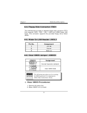
Make JCMOS1 (2-3) closed. Clear CMOS Jumper: JCMOS1 JCMOS1 1 3 1-2 Closed 1 3 2-3 Closed Assignment Normal Operation (default) Clear CMOS Data Clear CMOS Procedures: 1. Floppy Disk Connector: FDD1 The motherboard provides a standard floppy disk connector (FDC) that supports 360K, 720K, 1.2M, 1.44M and 2.88M floppy disk types. 4-4. Wake On LAN Header: JWOL1 Pin No. 1 2 3 Assignment +5V SB Ground Wake up 4-6. This connector supports the provided floppy drive ribbon cables. 4-5. Remove AC power line. 2.
Make JCMOS1 (2-3) closed. Clear CMOS Jumper: JCMOS1 JCMOS1 1 3 1-2 Closed 1 3 2-3 Closed Assignment Normal Operation (default) Clear CMOS Data Clear CMOS Procedures: 1. Floppy Disk Connector: FDD1 The motherboard provides a standard floppy disk connector (FDC) that supports 360K, 720K, 1.2M, 1.44M and 2.88M floppy disk types. 4-4. Wake On LAN Header: JWOL1 Pin No. 1 2 3 Assignment +5V SB Ground Wake up 4-6. This connector supports the provided floppy drive ribbon cables. 4-5. Remove AC power line. 2.
U8668 Grand user's manual
Page 23
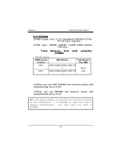
It is forbidden to 3.3V. !For the above settings, you can only use one kind of memory simultaneously. DRAM Type: 128MB/ 256MB/ 512MB DIMM Module (168 pin) Total Memory Size with unbuffer DIMMs !When you use DDR SDRAM, the memory power will automatically set to 2.5V. !When you use SDRAM, the memory power will automatically set to insert both kind of memory on this motherboard. 5-2 SDRAM DRAM Access Time: 3.3V Unbuffered SDRAM PC100/ PC133 Type required. You must insert only DDR or SDRAM.
It is forbidden to 3.3V. !For the above settings, you can only use one kind of memory simultaneously. DRAM Type: 128MB/ 256MB/ 512MB DIMM Module (168 pin) Total Memory Size with unbuffer DIMMs !When you use DDR SDRAM, the memory power will automatically set to 2.5V. !When you use SDRAM, the memory power will automatically set to insert both kind of memory on this motherboard. 5-2 SDRAM DRAM Access Time: 3.3V Unbuffered SDRAM PC100/ PC133 Type required. You must insert only DDR or SDRAM.
U8668 Grand user's manual
Page 26
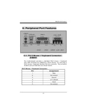
PS/2 Mouse / Keyboard Connector: JKBMS1 The motherboard provides a standard PS/2 mouse / Keyboard mini DIN connector for attaching a PS/2 mouse. You can plug a PS/2 mouse / Keyboard directly into this connector. Peripheral Port Features JKBMS1 PS/2 JUSBLAN1 Mouse LAN (Optional) JPRNT1 Parallel JAUD_GAME PS/2 Keyboard USB COM1 VGA1 Speaker Line In Mic Out In JCOM1 JVGA1 JSPKR1 JLIN1 JMIC1 6-1. The connector location and pin definition are shown below: PS/2 Mouse / Keyboard Connectors Pin 1 2 3 4 5 6 Assignment Data No connect Ground +5 V (fused) Clock No connect 6.
PS/2 Mouse / Keyboard Connector: JKBMS1 The motherboard provides a standard PS/2 mouse / Keyboard mini DIN connector for attaching a PS/2 mouse. You can plug a PS/2 mouse / Keyboard directly into this connector. Peripheral Port Features JKBMS1 PS/2 JUSBLAN1 Mouse LAN (Optional) JPRNT1 Parallel JAUD_GAME PS/2 Keyboard USB COM1 VGA1 Speaker Line In Mic Out In JCOM1 JVGA1 JSPKR1 JLIN1 JMIC1 6-1. The connector location and pin definition are shown below: PS/2 Mouse / Keyboard Connectors Pin 1 2 3 4 5 6 Assignment Data No connect Ground +5 V (fused) Clock No connect 6.
U8668 Grand user's manual
Page 30
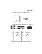
Your monitor will attach directly to JVGA1 connector on the motherboard. Pin No. Assignment Pin No. Assignment 1 Red 2 Green 3 Blue 4 NC 5 Ground 6 Ground 7 Ground 8 Ground 9 +5V 10 Ground 11 NC 12 DDC/Data 13 HSYNC 14 VSYNC 15 DDC/CLK 6-3-2Video Graphics Adapter Port: JVGA1 This motherboard has built in video facilities.
Your monitor will attach directly to JVGA1 connector on the motherboard. Pin No. Assignment Pin No. Assignment 1 Red 2 Green 3 Blue 4 NC 5 Ground 6 Ground 7 Ground 8 Ground 9 +5V 10 Ground 11 NC 12 DDC/Data 13 HSYNC 14 VSYNC 15 DDC/CLK 6-3-2Video Graphics Adapter Port: JVGA1 This motherboard has built in video facilities.

