
TForce 6100 user's manual
Page 2
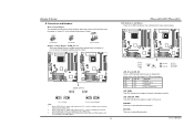
... Card and I CHAPTER 1: INTRODUCTION ...1 1.1 MOTHERBOARD FEATURES ...1 1.2 LAYOUT AND COMPONENTS: TFORCE 6100-939...2 1.3 LAYOUT AND COMPONENTS: TFORCE 6100 ...3 CHAPTER 2: HARDWARE INSTALLATIONS ...1 2.1 CPU ASSEMBLY ...1 A. Biostar T-Series TForce 6100-939/ TForce 6100 PACKAGE CHECKLIST ...I /O Slots:...4 B. Know your CPU version ...3 2.3 PERIPHERALS ...4 A. Connectors and Headers:...6 CHAPTER 3: USEFUL HELP...12 3.1 AWARD BIOS BEEP CODE...12 3.2 EXTRA INFORMATION ...12 A. Memory Space...3 C. DDR Installation Notice...3 D. Central Processing Unit (CPU) for...
... Card and I CHAPTER 1: INTRODUCTION ...1 1.1 MOTHERBOARD FEATURES ...1 1.2 LAYOUT AND COMPONENTS: TFORCE 6100-939...2 1.3 LAYOUT AND COMPONENTS: TFORCE 6100 ...3 CHAPTER 2: HARDWARE INSTALLATIONS ...1 2.1 CPU ASSEMBLY ...1 A. Biostar T-Series TForce 6100-939/ TForce 6100 PACKAGE CHECKLIST ...I /O Slots:...4 B. Know your CPU version ...3 2.3 PERIPHERALS ...4 A. Connectors and Headers:...6 CHAPTER 3: USEFUL HELP...12 3.1 AWARD BIOS BEEP CODE...12 3.2 EXTRA INFORMATION ...12 A. Memory Space...3 C. DDR Installation Notice...3 D. Central Processing Unit (CPU) for...
TForce 6100 user's manual
Page 3
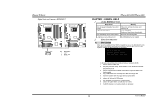
...'s Manual Two Ultra DMA 133/100/66/33 IDE connectors. TForce 6100 CPU Supports Socket 754. Two SATA ports. Biostar T-Series Chapter 1: Introduction 1.1 MOTHERBOARD FEATURES TForce 6100-939 CPU Supports Socket 939. Supports AMD Athlon 64 processor up to 3700+. Supports HyperTransport Technology up to 1600MT/s. Maximum memory space is 4GB, supporting 4 DIMM sockets. Environment Control initiatives, ...
...'s Manual Two Ultra DMA 133/100/66/33 IDE connectors. TForce 6100 CPU Supports Socket 754. Two SATA ports. Biostar T-Series Chapter 1: Introduction 1.1 MOTHERBOARD FEATURES TForce 6100-939 CPU Supports Socket 939. Supports AMD Athlon 64 processor up to 3700+. Supports HyperTransport Technology up to 1600MT/s. Maximum memory space is 4GB, supporting 4 DIMM sockets. Environment Control initiatives, ...
TForce 6100 user's manual
Page 7
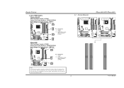
... the red wire is the positive and should be connected to pin#2, and the black wire is Ground and should be connected to GND. 2.2 SYSTEM MEMORY TForce 6100-939 2 DIMMB2 DIMMB1 DIMMA2 DIMMA1 DIMMB2 DIMMB1 TForce 6100-939/ TForce 6100 TForce 6100 User's Manual When connecting with Smart Fan Control utilities. It supports 3 pin head connector. Biostar T-Series C.
... the red wire is the positive and should be connected to pin#2, and the black wire is Ground and should be connected to GND. 2.2 SYSTEM MEMORY TForce 6100-939 2 DIMMB2 DIMMB1 DIMMA2 DIMMA1 DIMMB2 DIMMB1 TForce 6100-939/ TForce 6100 TForce 6100 User's Manual When connecting with Smart Fan Control utilities. It supports 3 pin head connector. Biostar T-Series C.
TForce 6100 user's manual
Page 8
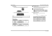
... on the slot such that the notch on the DIMM matches the break on the slot. 2. B. TForce 6100-939/ TForce 6100 C. Memory Space For TForce 6100-939 DIMM Socket Location DIMMA1 DIMMA2 DIMMB1 DIMMB2 DDR Module 128MB/256MB/512MB/1GB *1 128MB/256MB/512MB/1GB *1...TForce 6100 DIMM Socket Location DIMM1 DIMM2 DDR Module 128MB/256MB/512MB/1GB *1 128MB/256MB/512MB/1GB *1 Total Memory Size Max is properly seated. E, please follow the table below to Table 1 for CPU Revision) "SS" represents Single Side DDR memory module. DDR Modules 1. Total Memory Size (MB) Max is 2 GB. Biostar...
... on the slot such that the notch on the DIMM matches the break on the slot. 2. B. TForce 6100-939/ TForce 6100 C. Memory Space For TForce 6100-939 DIMM Socket Location DIMMA1 DIMMA2 DIMMB1 DIMMB2 DDR Module 128MB/256MB/512MB/1GB *1 128MB/256MB/512MB/1GB *1...TForce 6100 DIMM Socket Location DIMM1 DIMM2 DDR Module 128MB/256MB/512MB/1GB *1 128MB/256MB/512MB/1GB *1 Total Memory Size Max is properly seated. E, please follow the table below to Table 1 for CPU Revision) "SS" represents Single Side DDR memory module. DDR Modules 1. Total Memory Size (MB) Max is 2 GB. Biostar...
TForce 6100 user's manual
Page 11
Biostar T-Series B. TForce 6100-939 TForce 6100 JDDR_OV>3V 13 13 31 31 13 31 Pin 1-2 Close Pin 2-3 Close (Default) Note: 1. LED_5SB/LED_PWR: This LED indicates the system is an on Pin 1-2, memory voltage will be fixed at 3.3V automatically, and can be adjusted under CMOS ... LED_D2 LED_DIMM LED_PWR LED_D1 and LED_D2: These 2 LED indicate system power on . User's Manual TForce 6100-939/ TForce 6100 LED Indicators and Buttons There are 4 LED indicators on Pin 2-3, memory voltage can 't be manually adjusted under COMS setup. 3. When "JDDR_OV>3V" jumper cap is...
Biostar T-Series B. TForce 6100-939 TForce 6100 JDDR_OV>3V 13 13 31 31 13 31 Pin 1-2 Close Pin 2-3 Close (Default) Note: 1. LED_5SB/LED_PWR: This LED indicates the system is an on Pin 1-2, memory voltage will be fixed at 3.3V automatically, and can be adjusted under CMOS ... LED_D2 LED_DIMM LED_PWR LED_D1 and LED_D2: These 2 LED indicate system power on . User's Manual TForce 6100-939/ TForce 6100 LED Indicators and Buttons There are 4 LED indicators on Pin 2-3, memory voltage can 't be manually adjusted under COMS setup. 3. When "JDDR_OV>3V" jumper cap is...
TForce 6100 user's manual
Page 17
Biostar T-Series Digital Audio-out Connector: JSPDIF_OUT This connector allows users to restore the BIOS: 1. If the following message is invaded by two short beeps Video card not found or video card memory bad High-low siren ...Biostar website: www.biostar.com.tw 3. Download the Flash Utility "AWDFLASH.exe" from Biostar website. 4. System will shut down automatically One Short beep when system boots-up of the system, it means the BIOS contents are corrupted. TForce 6100-939 TForce 6100 JSPDIF_OUT 3 1 Pin Assignment 1 +5V 2 SPDIF OUT 3 Ground TForce 6100-939/ TForce 6100...
Biostar T-Series Digital Audio-out Connector: JSPDIF_OUT This connector allows users to restore the BIOS: 1. If the following message is invaded by two short beeps Video card not found or video card memory bad High-low siren ...Biostar website: www.biostar.com.tw 3. Download the Flash Utility "AWDFLASH.exe" from Biostar website. 4. System will shut down automatically One Short beep when system boots-up of the system, it means the BIOS contents are corrupted. TForce 6100-939 TForce 6100 JSPDIF_OUT 3 1 Pin Assignment 1 +5V 2 SPDIF OUT 3 Ground TForce 6100-939/ TForce 6100...


