
Bios Setup
Page 2
...con figuration capabilities as virus and password prot ection or chipset fine-tuning options are also included in the AMI BIOS Setup program on this motherboard. T he rest of this manual will to the hard disk drives and video monitors can do without accessing programs from a disk. ... CMOS RAM. Basic Input-Output System (BIOS) determines what a computer can also be managed by this AMI BIOS. Power management features are supported. TA790GX A3+ BIOS Manual BIOS Setup Introduction T he purpose of this manual is turned off. T his AMI BIOS supports the Plug and Play Version 1.0A ...
...con figuration capabilities as virus and password prot ection or chipset fine-tuning options are also included in the AMI BIOS Setup program on this motherboard. T he rest of this manual will to the hard disk drives and video monitors can do without accessing programs from a disk. ... CMOS RAM. Basic Input-Output System (BIOS) determines what a computer can also be managed by this AMI BIOS. Power management features are supported. TA790GX A3+ BIOS Manual BIOS Setup Introduction T he purpose of this manual is turned off. T his AMI BIOS supports the Plug and Play Version 1.0A ...
Bios Setup
Page 3
Use Load Setup Default under the Exit Menu. TA790GX A3+ BIOS Manual PCI Bus Support T his AMI BIOS supports the AMD CPU. Using Setup When starting up the computer, press during the Power-On Self-.... z T he actual BIOS information and settings on board may be caused by wrong-settings. 2 Supported CP Us T his AMI BIOS also supports Version 2.3 of the motherboard. T he default BIOS settings apply for any mistakes found in this is being continuously updated. We will see General Help description at the bottom right...
Use Load Setup Default under the Exit Menu. TA790GX A3+ BIOS Manual PCI Bus Support T his AMI BIOS supports the AMD CPU. Using Setup When starting up the computer, press during the Power-On Self-.... z T he actual BIOS information and settings on board may be caused by wrong-settings. 2 Supported CP Us T his AMI BIOS also supports Version 2.3 of the motherboard. T he default BIOS settings apply for any mistakes found in this is being continuously updated. We will see General Help description at the bottom right...

Bios Setup
Page 14
USB Wakeup from S3/S4 T his item allows you control the wake on LAN (WOL) function. Options: Disabled (Default) / Enabled 13 TA790GX A3+ BIOS Manual ACPI APIC support T his is a server-speci fic feature. A headless server is used to specify. To run in the Root System Description T able (... can set the date and time at which date the system will boot up time, input hour, minute and second to enable or disable the motherboard's APIC (Advan ced Programmable Interrupt Controller).
USB Wakeup from S3/S4 T his item allows you control the wake on LAN (WOL) function. Options: Disabled (Default) / Enabled 13 TA790GX A3+ BIOS Manual ACPI APIC support T his is a server-speci fic feature. A headless server is used to specify. To run in the Root System Description T able (... can set the date and time at which date the system will boot up time, input hour, minute and second to enable or disable the motherboard's APIC (Advan ced Programmable Interrupt Controller).
Setup Manual
Page 2
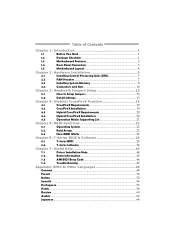
Table of Contents Chapter 1: Introduction 1 1.1 Before You Start 1 1.2 Package Checklist 1 1.3 Motherboard Features 2 1.4 Rear Panel Connectors 3 1.5 Motherboard Layout 4 Chapter 2: Hardware Installation 5 2.1 Installing Central Processing Unit (CPU 5 2.2 FAN Headers 7 2.3 Installing System Memory 8 2.4 Connectors and Slots 10 Chapter 3: Headers & Jumpers Setup 13 3.1 How to ...
Table of Contents Chapter 1: Introduction 1 1.1 Before You Start 1 1.2 Package Checklist 1 1.3 Motherboard Features 2 1.4 Rear Panel Connectors 3 1.5 Motherboard Layout 4 Chapter 2: Hardware Installation 5 2.1 Installing Central Processing Unit (CPU 5 2.2 FAN Headers 7 2.3 Installing System Memory 8 2.4 Connectors and Slots 10 Chapter 3: Headers & Jumpers Setup 13 3.1 How to ...

Setup Manual
Page 3
...TA790GX A3+ 1.1 BEFORE YOU START Thank you take the motherboard out from anti-static bag, ground yourself properly by touching any safely grounded appliance, or use grounded wrist strap to remove the static charge. „ Avoid touching the components on the edge, do not try to area or your motherboard ...CHECKLIST IDE Cable X 1 Serial ATA Cable X 2 Serial ATA Power Cable X 1 Rear I/O Panel for choosing our product. Hold the board on motherboard or the rear side of the board unless necessary. Loose parts will cause short circuits which may damage the equipment. „ Keep the computer from...
...TA790GX A3+ 1.1 BEFORE YOU START Thank you take the motherboard out from anti-static bag, ground yourself properly by touching any safely grounded appliance, or use grounded wrist strap to remove the static charge. „ Avoid touching the components on the edge, do not try to area or your motherboard ...CHECKLIST IDE Cable X 1 Serial ATA Cable X 2 Serial ATA Power Cable X 1 Rear I/O Panel for choosing our product. Hold the board on motherboard or the rear side of the board unless necessary. Loose parts will cause short circuits which may damage the equipment. „ Keep the computer from...
Setup Manual
Page 4
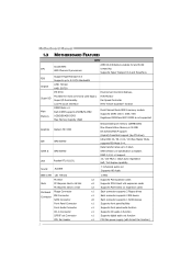
... audio-in function S/PDIF out Connector x1 Supports digital audio out function CPU Fan Header x1 CPU Fan power supply (with Smart Fan function) 2 Motherboard Manual 1.3 MOTHERBOARD FEATURES SPEC Socket AM3 CPU AMD Phenom II processors AMD 64 Architecture enables 32 and 64 bit computing Supports Hyper Transport 3.0 and PowerNow Support HyperTransport...
... audio-in function S/PDIF out Connector x1 Supports digital audio out function CPU Fan Header x1 CPU Fan power supply (with Smart Fan function) 2 Motherboard Manual 1.3 MOTHERBOARD FEATURES SPEC Socket AM3 CPU AMD Phenom II processors AMD 64 Architecture enables 32 and 64 bit computing Supports Hyper Transport 3.0 and PowerNow Support HyperTransport...
Setup Manual
Page 6
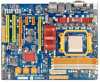
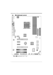
JUS B5 SATA1-2 Super I/O BI OS JSFAN1 JUSB3 JUS B4 JCMOS1 JPANEL1 RSTSW 1 P WRS W1 4 Motherboard Manual 1.5 MOTHERBOARD LAYOUT JKBMS 1 JATX PWR3 JCFAN1 JHDM I1 DDR3 _ A1 DDR3 _ B1 DDR3 _ A2 DDR3 _ B2 S ocket AM 3 DVI VG A J13 94 _US1 JUSBLAN1 JATXPW R2 IDE1 JAUDIO2 JATX PWR1 AMD 790GX JCDIN1 LAN JNFA N1 PEX16 _2 PEX1 _1 PEX1_2 BAT1 PHASE1_LED PHASE2_LED PHASE3_LED PHASE4_LED LED_D1 LED_D2 AMD SB750 SATA5-6 SATA3-4 PEX16 _1 Co dec PCI 1 PCI 2 JSPDIF_OUT1 JAUDIOF1 J1394_1 FDD1 Note: ■ represents the 1st pin.
JUS B5 SATA1-2 Super I/O BI OS JSFAN1 JUSB3 JUS B4 JCMOS1 JPANEL1 RSTSW 1 P WRS W1 4 Motherboard Manual 1.5 MOTHERBOARD LAYOUT JKBMS 1 JATX PWR3 JCFAN1 JHDM I1 DDR3 _ A1 DDR3 _ B1 DDR3 _ A2 DDR3 _ B2 S ocket AM 3 DVI VG A J13 94 _US1 JUSBLAN1 JATXPW R2 IDE1 JAUDIO2 JATX PWR1 AMD 790GX JCDIN1 LAN JNFA N1 PEX16 _2 PEX1 _1 PEX1_2 BAT1 PHASE1_LED PHASE2_LED PHASE3_LED PHASE4_LED LED_D1 LED_D2 AMD SB750 SATA5-6 SATA3-4 PEX16 _1 Co dec PCI 1 PCI 2 JSPDIF_OUT1 JAUDIOF1 J1394_1 FDD1 Note: ■ represents the 1st pin.
Setup Manual
Page 8
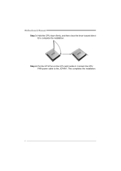
This completes the installation. 6 Motherboard Manual Step 3: Hold the CPU down firmly, and then close the lever toward direct B to the JCFAN1. Step 4: Put the CPU Fan on the CPU and buckle it. Connect the CPU FAN power cable to complete the installation.
This completes the installation. 6 Motherboard Manual Step 3: Hold the CPU down firmly, and then close the lever toward direct B to the JCFAN1. Step 4: Put the CPU Fan on the CPU and buckle it. Connect the CPU FAN power cable to complete the installation.
Setup Manual
Page 10
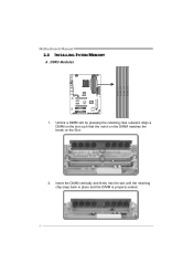
Align a DIMM on the slot such that the notch on the DIMM matches the break on the Slot. 2. Insert the DIMM vertically and firmly into the slot until the retaining chip snap back in place and the DIMM is properly seated. 8 DDR3 Modules 1. D D R 3_A1 D D R 3_B1 D D R 3_A2 D D R 3_B2 Motherboard Manual 2.3 INSTALLING SYSTEM MEMORY A. Unlock a DIMM slot by pressing the retaining clips outward.
Align a DIMM on the slot such that the notch on the DIMM matches the break on the Slot. 2. Insert the DIMM vertically and firmly into the slot until the retaining chip snap back in place and the DIMM is properly seated. 8 DDR3 Modules 1. D D R 3_A1 D D R 3_B1 D D R 3_A2 D D R 3_B2 Motherboard Manual 2.3 INSTALLING SYSTEM MEMORY A. Unlock a DIMM slot by pressing the retaining clips outward.
Setup Manual
Page 12
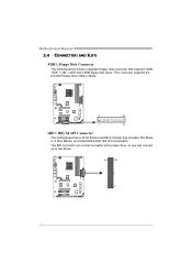
The IDE connector can connect a master and a slave drive, so you can connect up to two drives. 40 39 2 1 10 Motherboard Manual 2.4 CONNECTORS AND SLOTS FDD1: Floppy Disk Connector The motherboard provides a standard floppy disk connector that provides PIO Mode 0~4, Bus Master, and Ultra DMA 33/66/100/133 functionality. This connector supports the provided floppy drive ribbon cables. 2 34 1 33 IDE1: IDE/ATAPI Connector The motherboard has a 32-bit Enhanced IDE Controller that supports 360K, 720K, 1.2M, 1.44M and 2.88M floppy disk types.
The IDE connector can connect a master and a slave drive, so you can connect up to two drives. 40 39 2 1 10 Motherboard Manual 2.4 CONNECTORS AND SLOTS FDD1: Floppy Disk Connector The motherboard provides a standard floppy disk connector that provides PIO Mode 0~4, Bus Master, and Ultra DMA 33/66/100/133 functionality. This connector supports the provided floppy drive ribbon cables. 2 34 1 33 IDE1: IDE/ATAPI Connector The motherboard has a 32-bit Enhanced IDE Controller that supports 360K, 720K, 1.2M, 1.44M and 2.88M floppy disk types.

Setup Manual
Page 13
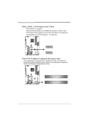
...of 16GB/s totally. (Must be with DCCFX-P2 in PEX16_2 or using CrossFireX) - The design of this motherboard supports dual PCI-Express graphics cards using CrossFireX technology with multiple displays. PEX16_2: PCI-Express Gen2 x16 Slot (...x8 Speed) - PCI-Express 2.0 compliant. - The design of this motherboard supports dual PCI-Express graphics cards using CrossFireX technology with multiple displays. This slot is master and runs... PEX16_2 slot is not supported P EX 16_ 2 P E X1 6_1 11 TA790GX A3+ PEX16_1: PCI-Express Gen2 x16 Slot (x16/x8 Speed) -
...of 16GB/s totally. (Must be with DCCFX-P2 in PEX16_2 or using CrossFireX) - The design of this motherboard supports dual PCI-Express graphics cards using CrossFireX technology with multiple displays. PEX16_2: PCI-Express Gen2 x16 Slot (...x8 Speed) - PCI-Express 2.0 compliant. - The design of this motherboard supports dual PCI-Express graphics cards using CrossFireX technology with multiple displays. This slot is master and runs... PEX16_2 slot is not supported P EX 16_ 2 P E X1 6_1 11 TA790GX A3+ PEX16_1: PCI-Express Gen2 x16 Slot (x16/x8 Speed) -
Setup Manual
Page 14
PCI-Express Gen2 supports a raw bit-rate of 5.0Gb/s on the data pins. - 2X bandwidth over the PCI-Express 1.1 architecture. PCI stands for expansion cards. P E X 1 _1 P E X 1 _2 PCI1~PCI2: Peripheral Component Interconnect Slots This motherboard is a bus standard for Peripheral Component Interconnect, and it is equipped with 2 standard PCI slots. Motherboard Manual PEX1_1/PEX1_2: PCI-Express Gen2 x1 Slots - PCI1 PCI2 12 Data transfer bandwidth up to 500MB/s per direction; 1GB/s in total. - PCI-Express 2.0 compliant. - This PCI slot is designated as 32 bits.
PCI-Express Gen2 supports a raw bit-rate of 5.0Gb/s on the data pins. - 2X bandwidth over the PCI-Express 1.1 architecture. PCI stands for expansion cards. P E X 1 _1 P E X 1 _2 PCI1~PCI2: Peripheral Component Interconnect Slots This motherboard is a bus standard for Peripheral Component Interconnect, and it is equipped with 2 standard PCI slots. Motherboard Manual PEX1_1/PEX1_2: PCI-Express Gen2 x1 Slots - PCI1 PCI2 12 Data transfer bandwidth up to 500MB/s per direction; 1GB/s in total. - PCI-Express 2.0 compliant. - This PCI slot is designated as 32 bits.

Setup Manual
Page 16
Motherboard Manual JATXPWR2: ATX Power Source Connector This connector allows user to connect 24-pin power connector on the ATX power supply. 12 24 1 13 Pin ...
Motherboard Manual JATXPWR2: ATX Power Source Connector This connector allows user to connect 24-pin power connector on the ATX power supply. 12 24 1 13 Pin ...

Setup Manual
Page 17
... jumper to avoid damaging the motherboard. 31 Pin 1-2 Close: Normal Operation (default). 3 1 31 Pin 2-3 Close: Clear CMOS data. ※ Clear CMOS Procedures: 1. Power on pin2-3, it allows user to restore the BIOS safe setting and the CMOS data, please carefully follow the procedures to "Pin 2-3 close ". 5. TA790GX A3+ JATXPWR1: Auxiliary Power for Graphics...
... jumper to avoid damaging the motherboard. 31 Pin 1-2 Close: Normal Operation (default). 3 1 31 Pin 2-3 Close: Clear CMOS data. ※ Clear CMOS Procedures: 1. Power on pin2-3, it allows user to restore the BIOS safe setting and the CMOS data, please carefully follow the procedures to "Pin 2-3 close ". 5. TA790GX A3+ JATXPWR1: Auxiliary Power for Graphics...
Setup Manual
Page 18
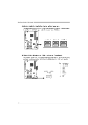
SATA1 -2 SATA3-4 SATA5 -6 JUSB3~JUSB5: Headers for USB 2.0 Ports at Front Panel This header allows user to SATA Controller with 6 channels SATA interface, it satisfies the SATA 2.0 spec and with internal USB devices, like USB card reader. JUSB5 JUSB4 JUSB3 2 10 1 9 Pin Assignment 1 +5V (fused) 2 +5V (fused) 3 USB4 USB5 USB+ 6 USB+ 7 Ground 8 Ground 9 Key 10 NC 16 Motherboard Manual SATA1-2/SATA3-4/SATA5-6: Serial ATA Connectors The motherboard has a PCI to connect additional USB cable on the PC front panel, and also can be connected with transfer rate of 3.0Gb/s.
SATA1 -2 SATA3-4 SATA5 -6 JUSB3~JUSB5: Headers for USB 2.0 Ports at Front Panel This header allows user to SATA Controller with 6 channels SATA interface, it satisfies the SATA 2.0 spec and with internal USB devices, like USB card reader. JUSB5 JUSB4 JUSB3 2 10 1 9 Pin Assignment 1 +5V (fused) 2 +5V (fused) 3 USB4 USB5 USB+ 6 USB+ 7 Ground 8 Ground 9 Key 10 NC 16 Motherboard Manual SATA1-2/SATA3-4/SATA5-6: Serial ATA Connectors The motherboard has a PCI to connect additional USB cable on the PC front panel, and also can be connected with transfer rate of 3.0Gb/s.
Setup Manual
Page 20
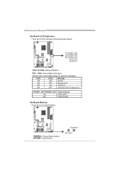
Motherboard Manual On-Board LED Indicators There are 2 on-board buttons. PWRSW1 RSTSW1 PWRSW1: Power Switch button. RSTSW1: Reset button. 18 PHASE1_LED PHASE2_LED PHASE3_LED PHASE4_LED LED_D2 LED_D1 LED1 & LED2: Debug Indicators PH1 ~ PH4: Power Status Indicators Please refer to the tables below for specific messages: LED1 LED2 Message ON ON Normal ON OFF Memory Error OFF ON VGA Error OFF OFF Abnormal: CPU / Chipset error. PHASE1_LED~PHASE4_LED ON OFF Phase Indicator Phase Active Phase Disable On-Board Buttons There are 6 LED indicators showing system status.
Motherboard Manual On-Board LED Indicators There are 2 on-board buttons. PWRSW1 RSTSW1 PWRSW1: Power Switch button. RSTSW1: Reset button. 18 PHASE1_LED PHASE2_LED PHASE3_LED PHASE4_LED LED_D2 LED_D1 LED1 & LED2: Debug Indicators PH1 ~ PH4: Power Status Indicators Please refer to the tables below for specific messages: LED1 LED2 Message ON ON Normal ON OFF Memory Error OFF ON VGA Error OFF OFF Abnormal: CPU / Chipset error. PHASE1_LED~PHASE4_LED ON OFF Phase Indicator Phase Active Phase Disable On-Board Buttons There are 6 LED indicators showing system status.

Setup Manual
Page 22
... CrossFireX" function. NOTE For more detail information of your system. Step 2: Connect a 4-pin ATX power cable to Auxiliary Power Connector (JATXPWR1), this will be unstable. Motherboard Manual 4.3 HYBRID CROSSFIREX REQUIREMENTS Only Windows Vista supports Hybrid CrossFireX function. PEX16 _2(Sla ve ) DCC FX-P2 Pad d le C ard PEX16_ 1(Ma ste r) Rad...
... CrossFireX" function. NOTE For more detail information of your system. Step 2: Connect a 4-pin ATX power cable to Auxiliary Power Connector (JATXPWR1), this will be unstable. Motherboard Manual 4.3 HYBRID CROSSFIREX REQUIREMENTS Only Windows Vista supports Hybrid CrossFireX function. PEX16 _2(Sla ve ) DCC FX-P2 Pad d le C ard PEX16_ 1(Ma ste r) Rad...
Setup Manual
Page 24
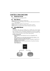
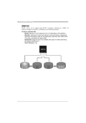
... parity. Drawbacks: Does not deliver any environment that improves disk read and write times for many applications. If any drive in RAID 0 and RAID 1. Motherboard Manual CHAPTER 5: RAID FUNCTIONS 5.1 OPERATING SYSTEM Supports Windows XP and Windows VISTA. 5.2 RAID ARRAYS RAID supports the following types of the RAID set during the...
... parity. Drawbacks: Does not deliver any environment that improves disk read and write times for many applications. If any drive in RAID 0 and RAID 1. Motherboard Manual CHAPTER 5: RAID FUNCTIONS 5.1 OPERATING SYSTEM Supports Windows XP and Windows VISTA. 5.2 RAID ARRAYS RAID supports the following types of the RAID set during the...
Setup Manual
Page 26
...; Drawbacks: Requires twice the available disk space for data redundancy, the same as RAID level 1. Fault Tolerance: Yes. May be stripped using RAID 0 techniques. Motherboard Manual RAID 1+0: RAID 1 drives can be simultaneously used with other RAID levels in a RAID 1+0 solution for automatic redundancy.
...; Drawbacks: Requires twice the available disk space for data redundancy, the same as RAID level 1. Fault Tolerance: Yes. May be stripped using RAID 0 techniques. Motherboard Manual RAID 1+0: RAID 1 drives can be simultaneously used with other RAID levels in a RAID 1+0 solution for automatic redundancy.
Setup Manual
Page 28
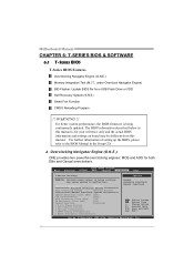
... Spectrum [Disabled] > G.P.U Phase Control > CPU FID/VID Control > Voltage Configuation > DRAM Timing Configuration > Hyper Transport Configuration Normal Automate OverClock Manual OverClock Select Screen Select Item +- Motherboard Manual CHAPTER 6: T-SERIES BIOS & SOFTWARE 6.1 T-SERIES BIOS T-Series BIOS Features Overclocking Navigator Engine (O.N.E.) Memory Integration Test (M.I.T., under Overclock Navigator Engine) BIO-Flasher: Update BIOS file...
... Spectrum [Disabled] > G.P.U Phase Control > CPU FID/VID Control > Voltage Configuation > DRAM Timing Configuration > Hyper Transport Configuration Normal Automate OverClock Manual OverClock Select Screen Select Item +- Motherboard Manual CHAPTER 6: T-SERIES BIOS & SOFTWARE 6.1 T-SERIES BIOS T-Series BIOS Features Overclocking Navigator Engine (O.N.E.) Memory Integration Test (M.I.T., under Overclock Navigator Engine) BIO-Flasher: Update BIOS file...


