
Bios Setup
Page 2
TA790GX A3+ BIOS Manual BIOS Setup Introduction T he purpose of the EPA Green PC specification. Basic Input-Output System (BIOS) determines what a computer can also be managed ... by Microso ft, Intel and T oshiba. 1 T he rest of this AMI BIOS. Power management features are supported. T his AMI BIOS supports Version 1.03 of this motherboard. APM Support T his AMI BIOS supports the Plug and Play Version 1.0A specification. Some additional features, such as keyboard, mouse, serial ports and disk drives...
TA790GX A3+ BIOS Manual BIOS Setup Introduction T he purpose of the EPA Green PC specification. Basic Input-Output System (BIOS) determines what a computer can also be managed ... by Microso ft, Intel and T oshiba. 1 T he rest of this AMI BIOS. Power management features are supported. T his AMI BIOS supports Version 1.03 of this motherboard. APM Support T his AMI BIOS supports the Plug and Play Version 1.0A specification. Some additional features, such as keyboard, mouse, serial ports and disk drives...
Bios Setup
Page 3
...ed without notice. General Help Navigation Keys Notice z T he content of this manual is subject to ensure optimum performan ce of the motherboard. T he actual BIOS information and settings on board may be slightly different from this manual is providing a brief description of the Intel ...the Power-On Self-Test (POST) to ensure system's compatibility and stability. z For better system perform ance, the BIOS firmware is supported. TA790GX A3+ BIOS Manual PCI Bus Support T his AMI BIOS supports the AMD CPU. Use Load Setup Default under the Exit Menu. T he BIOS ...
...ed without notice. General Help Navigation Keys Notice z T he content of this manual is subject to ensure optimum performan ce of the motherboard. T he actual BIOS information and settings on board may be slightly different from this manual is providing a brief description of the Intel ...the Power-On Self-Test (POST) to ensure system's compatibility and stability. z For better system perform ance, the BIOS firmware is supported. TA790GX A3+ BIOS Manual PCI Bus Support T his AMI BIOS supports the AMD CPU. Use Load Setup Default under the Exit Menu. T he BIOS ...

Bios Setup
Page 14
... system from Suspend mode. The APIC provides multiprocessor support, more IRQs and faster interrupt handling. A headless server is used to enable or disable the motherboard's APIC (Advan ced Programmable Interrupt Controller). RTC Alarm Time You can choose the system boot up . Options: Disabled (Default) / Enabled Power On...table Set this value to allow the ACPIBIOS to add a pointer to an OEMB table in headless mode, both BIOS and operating system (e.g. TA790GX A3+ BIOS Manual ACPI APIC support T his item allows you to enable or disabled the USB resume from S3/S4 function. To run in ...
... system from Suspend mode. The APIC provides multiprocessor support, more IRQs and faster interrupt handling. A headless server is used to enable or disable the motherboard's APIC (Advan ced Programmable Interrupt Controller). RTC Alarm Time You can choose the system boot up . Options: Disabled (Default) / Enabled Power On...table Set this value to allow the ACPIBIOS to add a pointer to an OEMB table in headless mode, both BIOS and operating system (e.g. TA790GX A3+ BIOS Manual ACPI APIC support T his item allows you to enable or disabled the USB resume from S3/S4 function. To run in ...
Setup Manual
Page 2
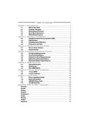
Table of Contents Chapter 1: Introduction 1 1.1 Before You Start 1 1.2 Package Checklist 1 1.3 Motherboard Features 2 1.4 Rear Panel Connectors 3 1.5 Motherboard Layout 4 Chapter 2: Hardware Installation 5 2.1 Installing Central Processing Unit (CPU 5 2.2 FAN Headers 7 2.3 Installing System Memory 8 2.4 Connectors and Slots 10 Chapter 3: Headers & Jumpers Setup 13 3.1 How to ...
Table of Contents Chapter 1: Introduction 1 1.1 Before You Start 1 1.2 Package Checklist 1 1.3 Motherboard Features 2 1.4 Rear Panel Connectors 3 1.5 Motherboard Layout 4 Chapter 2: Hardware Installation 5 2.1 Installing Central Processing Unit (CPU 5 2.2 FAN Headers 7 2.3 Installing System Memory 8 2.4 Connectors and Slots 10 Chapter 3: Headers & Jumpers Setup 13 3.1 How to ...

Setup Manual
Page 3
...anti-static bag, ground yourself properly by touching any unfastened small parts inside the case after installation. Hold the board on motherboard or the rear side of the board unless necessary. Loose parts will cause short circuits which may be different due to bend...remove the static charge. „ Avoid touching the components on the edge, do not try to area or your motherboard version. 1 CHAPTER 1: INTRODUCTION TA790GX A3+ 1.1 BEFORE YOU START Thank you take the motherboard out from dangerous area, such as heat source, humid air and water. 1.2 PACKAGE CHECKLIST IDE Cable X 1...
...anti-static bag, ground yourself properly by touching any unfastened small parts inside the case after installation. Hold the board on motherboard or the rear side of the board unless necessary. Loose parts will cause short circuits which may be different due to bend...remove the static charge. „ Avoid touching the components on the edge, do not try to area or your motherboard version. 1 CHAPTER 1: INTRODUCTION TA790GX A3+ 1.1 BEFORE YOU START Thank you take the motherboard out from dangerous area, such as heat source, humid air and water. 1.2 PACKAGE CHECKLIST IDE Cable X 1...
Setup Manual
Page 4
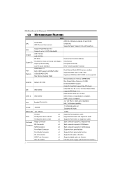
... 33 / 66 / 100 / 133 Bus Master Mode supports PIO Mode 0~4, SATA II AMD SB750 Data transfer rates up to 3 Gb/s. SATA Version 2.0 specification compliant. Motherboard Manual 1.3 MOTHERBOARD FEATURES SPEC Socket AM3 CPU AMD Phenom II processors AMD 64 Architecture enables 32 and 64 bit computing Supports Hyper Transport 3.0 and PowerNow Support HyperTransport...
... 33 / 66 / 100 / 133 Bus Master Mode supports PIO Mode 0~4, SATA II AMD SB750 Data transfer rates up to 3 Gb/s. SATA Version 2.0 specification compliant. Motherboard Manual 1.3 MOTHERBOARD FEATURES SPEC Socket AM3 CPU AMD Phenom II processors AMD 64 Architecture enables 32 and 64 bit computing Supports Hyper Transport 3.0 and PowerNow Support HyperTransport...
Setup Manual
Page 6
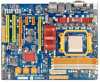
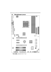
JUS B5 SATA1-2 Super I/O BI OS JSFAN1 JUSB3 JUS B4 JCMOS1 JPANEL1 RSTSW 1 P WRS W1 4 Motherboard Manual 1.5 MOTHERBOARD LAYOUT JKBMS 1 JATX PWR3 JCFAN1 JHDM I1 DDR3 _ A1 DDR3 _ B1 DDR3 _ A2 DDR3 _ B2 S ocket AM 3 DVI VG A J13 94 _US1 JUSBLAN1 JATXPW R2 IDE1 JAUDIO2 JATX PWR1 AMD 790GX JCDIN1 LAN JNFA N1 PEX16 _2 PEX1 _1 PEX1_2 BAT1 PHASE1_LED PHASE2_LED PHASE3_LED PHASE4_LED LED_D1 LED_D2 AMD SB750 SATA5-6 SATA3-4 PEX16 _1 Co dec PCI 1 PCI 2 JSPDIF_OUT1 JAUDIOF1 J1394_1 FDD1 Note: ■ represents the 1st pin.
JUS B5 SATA1-2 Super I/O BI OS JSFAN1 JUSB3 JUS B4 JCMOS1 JPANEL1 RSTSW 1 P WRS W1 4 Motherboard Manual 1.5 MOTHERBOARD LAYOUT JKBMS 1 JATX PWR3 JCFAN1 JHDM I1 DDR3 _ A1 DDR3 _ B1 DDR3 _ A2 DDR3 _ B2 S ocket AM 3 DVI VG A J13 94 _US1 JUSBLAN1 JATXPW R2 IDE1 JAUDIO2 JATX PWR1 AMD 790GX JCDIN1 LAN JNFA N1 PEX16 _2 PEX1 _1 PEX1_2 BAT1 PHASE1_LED PHASE2_LED PHASE3_LED PHASE4_LED LED_D1 LED_D2 AMD SB750 SATA5-6 SATA3-4 PEX16 _1 Co dec PCI 1 PCI 2 JSPDIF_OUT1 JAUDIOF1 J1394_1 FDD1 Note: ■ represents the 1st pin.
Setup Manual
Page 8
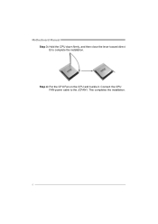
Step 4: Put the CPU Fan on the CPU and buckle it. This completes the installation. 6 Connect the CPU FAN power cable to complete the installation. Motherboard Manual Step 3: Hold the CPU down firmly, and then close the lever toward direct B to the JCFAN1.
Step 4: Put the CPU Fan on the CPU and buckle it. This completes the installation. 6 Connect the CPU FAN power cable to complete the installation. Motherboard Manual Step 3: Hold the CPU down firmly, and then close the lever toward direct B to the JCFAN1.
Setup Manual
Page 10
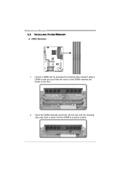
Insert the DIMM vertically and firmly into the slot until the retaining chip snap back in place and the DIMM is properly seated. 8 DDR3 Modules 1. Align a DIMM on the slot such that the notch on the DIMM matches the break on the Slot. 2. D D R 3_A1 D D R 3_B1 D D R 3_A2 D D R 3_B2 Motherboard Manual 2.3 INSTALLING SYSTEM MEMORY A. Unlock a DIMM slot by pressing the retaining clips outward.
Insert the DIMM vertically and firmly into the slot until the retaining chip snap back in place and the DIMM is properly seated. 8 DDR3 Modules 1. Align a DIMM on the slot such that the notch on the DIMM matches the break on the Slot. 2. D D R 3_A1 D D R 3_B1 D D R 3_A2 D D R 3_B2 Motherboard Manual 2.3 INSTALLING SYSTEM MEMORY A. Unlock a DIMM slot by pressing the retaining clips outward.
Setup Manual
Page 12
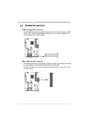
Motherboard Manual 2.4 CONNECTORS AND SLOTS FDD1: Floppy Disk Connector The motherboard provides a standard floppy disk connector that provides PIO Mode 0~4, Bus Master, and Ultra DMA 33/66/100/133 functionality. This connector supports the provided floppy drive ribbon cables. 2 34 1 33 IDE1: IDE/ATAPI Connector The motherboard has a 32-bit Enhanced IDE Controller that supports 360K, 720K, 1.2M, 1.44M and 2.88M floppy disk types. The IDE connector can connect a master and a slave drive, so you can connect up to two drives. 40 39 2 1 10
Motherboard Manual 2.4 CONNECTORS AND SLOTS FDD1: Floppy Disk Connector The motherboard provides a standard floppy disk connector that provides PIO Mode 0~4, Bus Master, and Ultra DMA 33/66/100/133 functionality. This connector supports the provided floppy drive ribbon cables. 2 34 1 33 IDE1: IDE/ATAPI Connector The motherboard has a 32-bit Enhanced IDE Controller that supports 360K, 720K, 1.2M, 1.44M and 2.88M floppy disk types. The IDE connector can connect a master and a slave drive, so you can connect up to two drives. 40 39 2 1 10

Setup Manual
Page 13
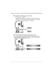
... runs with x8 speed. - PCI-Express Gen2 supports a raw bit-rate of 4GB/s simultaneously per direction, for graphics or video cards. TA790GX A3+ PEX16_1: PCI-Express Gen2 x16 Slot (x16/x8 Speed) - x16 Speed Mode: Maximum theoretical realized bandwidth of 8GB/s simultaneously per direction,...direction, for an aggregate of this slot run with multiple displays. PEX16_1 slot is slave when using CrossFireX) - To make this motherboard supports dual PCI-Express graphics cards using CrossFireX technology with x16 speed, please insert the Paddle Card DCCFX-P2 into PEX16_2. The...
... runs with x8 speed. - PCI-Express Gen2 supports a raw bit-rate of 4GB/s simultaneously per direction, for graphics or video cards. TA790GX A3+ PEX16_1: PCI-Express Gen2 x16 Slot (x16/x8 Speed) - x16 Speed Mode: Maximum theoretical realized bandwidth of 8GB/s simultaneously per direction,...direction, for an aggregate of this slot run with multiple displays. PEX16_1 slot is slave when using CrossFireX) - To make this motherboard supports dual PCI-Express graphics cards using CrossFireX technology with x16 speed, please insert the Paddle Card DCCFX-P2 into PEX16_2. The...
Setup Manual
Page 14
Data transfer bandwidth up to 500MB/s per direction; 1GB/s in total. - PCI-Express Gen2 supports a raw bit-rate of 5.0Gb/s on the data pins. - 2X bandwidth over the PCI-Express 1.1 architecture. PCI stands for Peripheral Component Interconnect, and it is designated as 32 bits. This PCI slot is a bus standard for expansion cards. Motherboard Manual PEX1_1/PEX1_2: PCI-Express Gen2 x1 Slots - PCI1 PCI2 12 P E X 1 _1 P E X 1 _2 PCI1~PCI2: Peripheral Component Interconnect Slots This motherboard is equipped with 2 standard PCI slots. PCI-Express 2.0 compliant. -
Data transfer bandwidth up to 500MB/s per direction; 1GB/s in total. - PCI-Express Gen2 supports a raw bit-rate of 5.0Gb/s on the data pins. - 2X bandwidth over the PCI-Express 1.1 architecture. PCI stands for Peripheral Component Interconnect, and it is designated as 32 bits. This PCI slot is a bus standard for expansion cards. Motherboard Manual PEX1_1/PEX1_2: PCI-Express Gen2 x1 Slots - PCI1 PCI2 12 P E X 1 _1 P E X 1 _2 PCI1~PCI2: Peripheral Component Interconnect Slots This motherboard is equipped with 2 standard PCI slots. PCI-Express 2.0 compliant. -

Setup Manual
Page 16
Motherboard Manual JATXPWR2: ATX Power Source Connector This connector allows user to connect 24-pin power connector on the ATX power supply. 12 24 1 13 Pin ...
Motherboard Manual JATXPWR2: ATX Power Source Connector This connector allows user to connect 24-pin power connector on the ATX power supply. 12 24 1 13 Pin ...

Setup Manual
Page 17
... to "Pin 1-2 close ". 3. Exclusive power for graphics cards. Set the jumper to avoid damaging the motherboard. 31 Pin 1-2 Close: Normal Operation (default). 3 1 31 Pin 2-3 Close: Clear CMOS data. ※ Clear CMOS Procedures: 1. Remove AC power line. 2. TA790GX A3+ JATXPWR1: Auxiliary Power for Graphics This connector is an auxiliary power connection for the graphics...
... to "Pin 1-2 close ". 3. Exclusive power for graphics cards. Set the jumper to avoid damaging the motherboard. 31 Pin 1-2 Close: Normal Operation (default). 3 1 31 Pin 2-3 Close: Clear CMOS data. ※ Clear CMOS Procedures: 1. Remove AC power line. 2. TA790GX A3+ JATXPWR1: Auxiliary Power for Graphics This connector is an auxiliary power connection for the graphics...
Setup Manual
Page 18
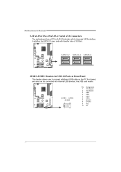
SATA1 -2 SATA3-4 SATA5 -6 JUSB3~JUSB5: Headers for USB 2.0 Ports at Front Panel This header allows user to SATA Controller with 6 channels SATA interface, it satisfies the SATA 2.0 spec and with internal USB devices, like USB card reader. JUSB5 JUSB4 JUSB3 2 10 1 9 Pin Assignment 1 +5V (fused) 2 +5V (fused) 3 USB4 USB5 USB+ 6 USB+ 7 Ground 8 Ground 9 Key 10 NC 16 Motherboard Manual SATA1-2/SATA3-4/SATA5-6: Serial ATA Connectors The motherboard has a PCI to connect additional USB cable on the PC front panel, and also can be connected with transfer rate of 3.0Gb/s.
SATA1 -2 SATA3-4 SATA5 -6 JUSB3~JUSB5: Headers for USB 2.0 Ports at Front Panel This header allows user to SATA Controller with 6 channels SATA interface, it satisfies the SATA 2.0 spec and with internal USB devices, like USB card reader. JUSB5 JUSB4 JUSB3 2 10 1 9 Pin Assignment 1 +5V (fused) 2 +5V (fused) 3 USB4 USB5 USB+ 6 USB+ 7 Ground 8 Ground 9 Key 10 NC 16 Motherboard Manual SATA1-2/SATA3-4/SATA5-6: Serial ATA Connectors The motherboard has a PCI to connect additional USB cable on the PC front panel, and also can be connected with transfer rate of 3.0Gb/s.
Setup Manual
Page 20
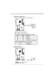
PWRSW1 RSTSW1 PWRSW1: Power Switch button. RSTSW1: Reset button. 18 PHASE1_LED~PHASE4_LED ON OFF Phase Indicator Phase Active Phase Disable On-Board Buttons There are 6 LED indicators showing system status. PHASE1_LED PHASE2_LED PHASE3_LED PHASE4_LED LED_D2 LED_D1 LED1 & LED2: Debug Indicators PH1 ~ PH4: Power Status Indicators Please refer to the tables below for specific messages: LED1 LED2 Message ON ON Normal ON OFF Memory Error OFF ON VGA Error OFF OFF Abnormal: CPU / Chipset error. Motherboard Manual On-Board LED Indicators There are 2 on-board buttons.
PWRSW1 RSTSW1 PWRSW1: Power Switch button. RSTSW1: Reset button. 18 PHASE1_LED~PHASE4_LED ON OFF Phase Indicator Phase Active Phase Disable On-Board Buttons There are 6 LED indicators showing system status. PHASE1_LED PHASE2_LED PHASE3_LED PHASE4_LED LED_D2 LED_D1 LED1 & LED2: Debug Indicators PH1 ~ PH4: Power Status Indicators Please refer to the tables below for specific messages: LED1 LED2 Message ON ON Normal ON OFF Memory Error OFF ON VGA Error OFF OFF Abnormal: CPU / Chipset error. Motherboard Manual On-Board LED Indicators There are 2 on-board buttons.

Setup Manual
Page 22
Motherboard Manual 4.3 HYBRID CROSSFIREX REQUIREMENTS Only Windows Vista supports Hybrid CrossFireX function. The graphics card driver should support Hybrid CrossFireX technology. A power supply above 450W is ...
Motherboard Manual 4.3 HYBRID CROSSFIREX REQUIREMENTS Only Windows Vista supports Hybrid CrossFireX function. The graphics card driver should support Hybrid CrossFireX technology. A power supply above 450W is ...
Setup Manual
Page 24
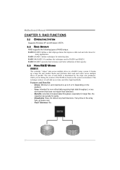
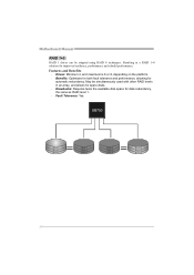
Motherboard Manual CHAPTER 5: RAID FUNCTIONS 5.1 OPERATING SYSTEM Supports Windows XP and Windows VISTA. 5.2 RAID ARRAYS RAID supports the following types of disk capacity. 5.3 HOW RAID WORKS ...
Motherboard Manual CHAPTER 5: RAID FUNCTIONS 5.1 OPERATING SYSTEM Supports Windows XP and Windows VISTA. 5.2 RAID ARRAYS RAID supports the following types of disk capacity. 5.3 HOW RAID WORKS ...
Setup Manual
Page 26
... on the platform. Benefits: Optimizes for both fault tolerance and performance, allowing for data redundancy, the same as RAID level 1. Fault Tolerance: Yes. Motherboard Manual RAID 1+0: RAID 1 drives can be simultaneously used with other RAID levels in a RAID 1+0 solution for improved resiliency, performance and rebuild performance. Resulting in an...
... on the platform. Benefits: Optimizes for both fault tolerance and performance, allowing for data redundancy, the same as RAID level 1. Fault Tolerance: Yes. Motherboard Manual RAID 1+0: RAID 1 drives can be simultaneously used with other RAID levels in a RAID 1+0 solution for improved resiliency, performance and rebuild performance. Resulting in an...
Setup Manual
Page 28
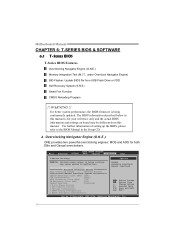
... and AOS for your reference only and the actual BIOS information and settings on board may cause system to the BIOS Manual in this manual. Motherboard Manual CHAPTER 6: T-SERIES BIOS & SOFTWARE 6.1 T-SERIES BIOS T-Series BIOS Features Overclocking Navigator Engine (O.N.E.) Memory Integration Test (M.I.T., under Overclock Navigator Engine) BIO-Flasher: Update BIOS file...
... and AOS for your reference only and the actual BIOS information and settings on board may cause system to the BIOS Manual in this manual. Motherboard Manual CHAPTER 6: T-SERIES BIOS & SOFTWARE 6.1 T-SERIES BIOS T-Series BIOS Features Overclocking Navigator Engine (O.N.E.) Memory Integration Test (M.I.T., under Overclock Navigator Engine) BIO-Flasher: Update BIOS file...


