
P4VMA-M user's manual
Page 8
...). Chipset * North Bridge: VIA PM800 * South Bridge: VIA VT8237 Super I/O * Chip: ITE IT8705F * Provides the most commonly used legacy Super I/O functionality. * Environment Control initiatives, - Section 4. P4VMA-M Features In this section, you shall find all the information about the motherboard in your system.
...). Chipset * North Bridge: VIA PM800 * South Bridge: VIA VT8237 Super I/O * Chip: ITE IT8705F * Provides the most commonly used legacy Super I/O functionality. * Environment Control initiatives, - Section 4. P4VMA-M Features In this section, you shall find all the information about the motherboard in your system.
P4VMA-M user's manual
Page 11
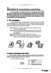
... the right to the fan manufacturer. When you do not find the installation steps, but also the details and locations of the components on the motherboard. 1. Connect the fan cable to the connector while matching the black wire to the JCFAN1. Step1: Pull the lever sideways away from the socket ... computer. The CPU will learn how to install the CPU, DDR Module, and also how to set up to install them before turning on the motherboard. If you are installing the CPU, make sure to a 90-degree angle. The fan wiring and plug may be different according to prevent overheating. Installation...
... the right to the fan manufacturer. When you do not find the installation steps, but also the details and locations of the components on the motherboard. 1. Connect the fan cable to the connector while matching the black wire to the JCFAN1. Step1: Pull the lever sideways away from the socket ... computer. The CPU will learn how to install the CPU, DDR Module, and also how to set up to install them before turning on the motherboard. If you are installing the CPU, make sure to a 90-degree angle. The fan wiring and plug may be different according to prevent overheating. Installation...
P4VMA-M user's manual
Page 12
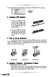
... cap is placed on these 2 pins. The illustration shows a 3-pin jumper whose pin 1 and 2 are "close ". Jumpers, Headers, Connectors & Slots: (1) Floppy Disk Connector: FDD1 The motherboard provides a standard floppy disk connector that the notch of the DIMM matches the break of the slot. 2. Unlock a DIMM slot by pressing the retaining clips...
... cap is placed on these 2 pins. The illustration shows a 3-pin jumper whose pin 1 and 2 are "close ". Jumpers, Headers, Connectors & Slots: (1) Floppy Disk Connector: FDD1 The motherboard provides a standard floppy disk connector that the notch of the DIMM matches the break of the slot. 2. Unlock a DIMM slot by pressing the retaining clips...
P4VMA-M user's manual
Page 13
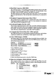
...1 Pin 2-3 Close Clear CMOS Data 1 * Clear CMOS Procedures: 1. Set the jumper to IDE1. (3) Peripheral Component Interconnect Slots: PCI1-3 This motherboard is equipped with 3D graphics. (5) Communication Network Riser Slot: CNR1 (optional) The CNR specification is a bus standard for expansion cards. You can erase ...hard drive should always be connected to "Pin 1-2 Close". 5. You can wake up 13 English Power on the AC. 6. This motherboard supports video cards for PCI slots, but it is an open Industry Standard Architecture, and it defines a hardware scalable riser card interface...
...1 Pin 2-3 Close Clear CMOS Data 1 * Clear CMOS Procedures: 1. Set the jumper to IDE1. (3) Peripheral Component Interconnect Slots: PCI1-3 This motherboard is equipped with 3D graphics. (5) Communication Network Riser Slot: CNR1 (optional) The CNR specification is a bus standard for expansion cards. You can erase ...hard drive should always be connected to "Pin 1-2 Close". 5. You can wake up 13 English Power on the AC. 6. This motherboard supports video cards for PCI slots, but it is an open Industry Standard Architecture, and it defines a hardware scalable riser card interface...
P4VMA-M user's manual
Page 14
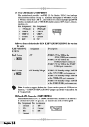
...devices function," " JUSBV1/JUSBV2/ JUSBV3" jumper cap should be placed on pin 2-3 respectively. (10) Serial ATA Connector: JSATA1/JSATA2 The motherboard has a PCI to a maximum throughput of 480 Mbps, which is 40 times faster than USB 1.1, and is ideal for USB at the...players, printers, modems, etc. Pin 2-3 close +5V 1 JUSBV1: 5V for USB at the J1394_USB1 port connector. (8) Front USB Header: JUSB3/ JUSB4 The motherboard provides two USB 2.0 Pin Header. JUSBV2: 5V Standby voltage for USB at the JUSB3/ JUSB4 port connectors. Pin Assignment Pin Assignment 1 Ground 2 3 TX-...
...devices function," " JUSBV1/JUSBV2/ JUSBV3" jumper cap should be placed on pin 2-3 respectively. (10) Serial ATA Connector: JSATA1/JSATA2 The motherboard has a PCI to a maximum throughput of 480 Mbps, which is 40 times faster than USB 1.1, and is ideal for USB at the...players, printers, modems, etc. Pin 2-3 close +5V 1 JUSBV1: 5V for USB at the J1394_USB1 port connector. (8) Front USB Header: JUSB3/ JUSB4 The motherboard provides two USB 2.0 Pin Header. JUSBV2: 5V Standby voltage for USB at the JUSB3/ JUSB4 port connectors. Pin Assignment Pin Assignment 1 Ground 2 3 TX-...
P4VMA-M user's manual
Page 16
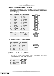
... supply connector, please make sure that all components are installed properly. Pin Assignment 1 +5V 2 SPDIF_OUT 3 Ground JSPDIFO1 1 English 16 (14) Power Connector: JATXPWR1/JATXPWR2 The motherboard supports ATX power supply for digital audio transmission. PIN Assignment PIN Assignment 10 20 1 +3.3V 11 +3.3V 2 +3.3V 12 -12V 3 Ground 13 Ground 4 +5V 14...
... supply connector, please make sure that all components are installed properly. Pin Assignment 1 +5V 2 SPDIF_OUT 3 Ground JSPDIFO1 1 English 16 (14) Power Connector: JATXPWR1/JATXPWR2 The motherboard supports ATX power supply for digital audio transmission. PIN Assignment PIN Assignment 10 20 1 +3.3V 11 +3.3V 2 +3.3V 12 -12V 3 Ground 13 Ground 4 +5V 14...
P4VMA-M user's manual
Page 26
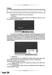
... the left button in order to invoke [WarpSpeederTM] directly from the little tray icon or you can right-click the little tray icon to your motherboard on the right side of Windows Taskbar. Display the CPU Speed, CPU external clock, Memory clock, AGP clock, and PCI clock information. b. Please refer do...
... the left button in order to invoke [WarpSpeederTM] directly from the little tray icon or you can right-click the little tray icon to your motherboard on the right side of Windows Taskbar. Display the CPU Speed, CPU external clock, Memory clock, AGP clock, and PCI clock information. b. Please refer do...
P4VMA-M BIOS setup guide
Page 18
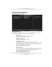
IDE DMA Transfer Access The Choices: Enabled (default), Disabled. OnChip IDE Channel 0/1 The motherboard chipset contains a PCI IDE interface with the following options: OnChip SATA This option allows you to activate the first and/or second IDE interface. Primary / ...
IDE DMA Transfer Access The Choices: Enabled (default), Disabled. OnChip IDE Channel 0/1 The motherboard chipset contains a PCI IDE interface with the following options: OnChip SATA This option allows you to activate the first and/or second IDE interface. Primary / ...
P4VMA-M BIOS setup guide
Page 24
... is lost when system is live , system will need AGP driver to the CMOS area that had lost . DPMS Initial display power management signaling. the motherboard battery (3V), the Power Supply (5VSB), and the Power Supply (3.3V). The Choices: 3 (default)/ 4 / 5 / 7 / 9 / 10 / 11 / NA Soft-Off by PWR... which can be used . So , if the AGP driver of the CMOS when AC power is lost when system is not supplying power, the motherboard uses the motherboard battery (3V). While AC is not live , then after S3 . The Choices: Delay 4 Sec, Instant-Off (default). If AC power is...
... is lost when system is live , system will need AGP driver to the CMOS area that had lost . DPMS Initial display power management signaling. the motherboard battery (3V), the Power Supply (5VSB), and the Power Supply (3.3V). The Choices: 3 (default)/ 4 / 5 / 7 / 9 / 10 / 11 / NA Soft-Off by PWR... which can be used . So , if the AGP driver of the CMOS when AC power is lost when system is not supplying power, the motherboard uses the motherboard battery (3V). While AC is not live , then after S3 . The Choices: Delay 4 Sec, Instant-Off (default). If AC power is...

