
P4VMA-M user's manual
Page 8
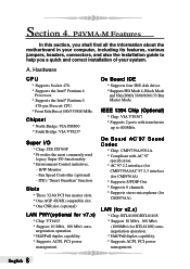
... IDE * Supports four IDE disk drives. * Supports PIO Mode 4, Block Mode and Ultra DMA 33/66/100/133 Bus Master Mode. P4VMA-M Features In this section, you shall find all the information about the motherboard in your computer, including its features, various jumpers, headers, connectors, and also the installation guide to 400Mb/s.
... IDE * Supports four IDE disk drives. * Supports PIO Mode 4, Block Mode and Ultra DMA 33/66/100/133 Bus Master Mode. P4VMA-M Features In this section, you shall find all the information about the motherboard in your computer, including its features, various jumpers, headers, connectors, and also the installation guide to 400Mb/s.
P4VMA-M user's manual
Page 11
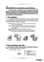
Step4: Put the CPU fan on the right to a 90-degree angle. CPU Installation The motherboard supports the Intel Pentium® Socket-478 processor. The CPU will learn how to install the CPU, DDR Module, and also how to set up ... Headers: JCFAN1 1 Pin Assignment 1 Ground 2 +12V 3 FAN RPM Rate Sense 11 English Connect the CPU fan power cable to install them before turning on the motherboard. 1. Section 6. Installation and Setup In this section, you find the cooling fan, contact your dealer and make sure the CPU has a cooling fan attached on...
Step4: Put the CPU fan on the right to a 90-degree angle. CPU Installation The motherboard supports the Intel Pentium® Socket-478 processor. The CPU will learn how to install the CPU, DDR Module, and also how to set up ... Headers: JCFAN1 1 Pin Assignment 1 Ground 2 +12V 3 FAN RPM Rate Sense 11 English Connect the CPU fan power cable to install them before turning on the motherboard. 1. Section 6. Installation and Setup In this section, you find the cooling fan, contact your dealer and make sure the CPU has a cooling fan attached on...
P4VMA-M user's manual
Page 12
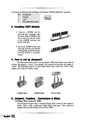
How to the slot in place and the Dimm is "close". Jumpers, Headers, Connectors & Slots: (1) Floppy Disk Connector: FDD1 The motherboard provides a standard floppy disk connector that the notch of the DIMM matches the break of the slot. 2. Installing DDR Module 1. Align a DIMM to set up ...
How to the slot in place and the Dimm is "close". Jumpers, Headers, Connectors & Slots: (1) Floppy Disk Connector: FDD1 The motherboard provides a standard floppy disk connector that the notch of the DIMM matches the break of the slot. 2. Installing DDR Module 1. Align a DIMM to set up ...
P4VMA-M user's manual
Page 13
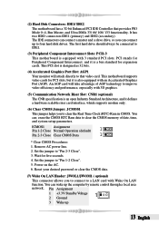
...provides PIO Mode 0~4, Bus Master, and Ultra DMA 33/ 66/ 100/ 133 functionality. (2) Hard Disk Connectors: IDE1/ IDE2 The motherboard has a 32-bit Enhanced PCI IDE Controller that video card. An AGP card will attach directly to improve video efficiency and performance, especially...3 Wake up the computer by remote control through a local area network. It has two HDD connectors IDE1 (primary) and IDE2 (secondary). This motherboard supports video cards for PCI slots, but it defines a hardware scalable riser card interface, which supports modem only. (6) Clear CMOS Jumper: JCMOS1 ...
...provides PIO Mode 0~4, Bus Master, and Ultra DMA 33/ 66/ 100/ 133 functionality. (2) Hard Disk Connectors: IDE1/ IDE2 The motherboard has a 32-bit Enhanced PCI IDE Controller that video card. An AGP card will attach directly to improve video efficiency and performance, especially...3 Wake up the computer by remote control through a local area network. It has two HDD connectors IDE1 (primary) and IDE2 (secondary). This motherboard supports video cards for PCI slots, but it defines a hardware scalable riser card interface, which supports modem only. (6) Clear CMOS Jumper: JCMOS1 ...
P4VMA-M user's manual
Page 14
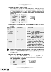
... via USB devices function," " JUSBV1/JUSBV2/ JUSBV3" jumper cap should be placed on pin 2-3 respectively. (10) Serial ATA Connector: JSATA1/JSATA2 The motherboard has a PCI to a maximum throughput of 480 Mbps, which is 40 times faster than USB 1.1, and is ideal for connecting high-speed USB interface... port connectors. Pin Assignment Pin Assignment 1 Ground 2 3 TX- 4 TX+ Ground 1 5 RX- 6 RX+ 7 Ground English 14 (8) Front USB Header: JUSB3/ JUSB4 The motherboard provides two USB 2.0 Pin Header. It satisfies the SATA 1.0 spec and can transfer data with 2 channels STAT interface.
... via USB devices function," " JUSBV1/JUSBV2/ JUSBV3" jumper cap should be placed on pin 2-3 respectively. (10) Serial ATA Connector: JSATA1/JSATA2 The motherboard has a PCI to a maximum throughput of 480 Mbps, which is 40 times faster than USB 1.1, and is ideal for connecting high-speed USB interface... port connectors. Pin Assignment Pin Assignment 1 Ground 2 3 TX- 4 TX+ Ground 1 5 RX- 6 RX+ 7 Ground English 14 (8) Front USB Header: JUSB3/ JUSB4 The motherboard provides two USB 2.0 Pin Header. It satisfies the SATA 1.0 spec and can transfer data with 2 channels STAT interface.
P4VMA-M user's manual
Page 16
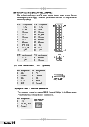
... supply connector, please make sure that all components are installed properly. Pin Assignment 1 +5V 2 SPDIF_OUT 3 Ground JSPDIFO1 1 English 16 (14) Power Connector: JATXPWR1/JATXPWR2 The motherboard supports ATX power supply for digital audio transmission.
... supply connector, please make sure that all components are installed properly. Pin Assignment 1 +5V 2 SPDIF_OUT 3 Ground JSPDIFO1 1 English 16 (14) Power Connector: JATXPWR1/JATXPWR2 The motherboard supports ATX power supply for digital audio transmission.
P4VMA-M user's manual
Page 26
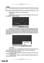
... this user manual will see is responsible for invoking respective panels. the utility's first window you can right-click the little tray icon to your motherboard on tray icon and "Exit" item will close Tray Icon utility if selected. 2. Contains About, Voltage, Overclock, and Hardware Monitor Buttons for conveniently invoking [WarpSpeederTM...
... this user manual will see is responsible for invoking respective panels. the utility's first window you can right-click the little tray icon to your motherboard on tray icon and "Exit" item will close Tray Icon utility if selected. 2. Contains About, Voltage, Overclock, and Hardware Monitor Buttons for conveniently invoking [WarpSpeederTM...
P4VMA-M BIOS setup guide
Page 18
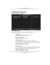
...), Disabled. IDE Prefetch Mode The "onboard" IDE drive interfaces supports IDE prefetching for two IDE channels. The Choices: Enabled (default), Disabled. OnChip IDE Channel 0/1 The motherboard chipset contains a PCI IDE interface with the following options: OnChip SATA This option allows you a submenu with support for faster drive access. The Choices: Enabled...
...), Disabled. IDE Prefetch Mode The "onboard" IDE drive interfaces supports IDE prefetching for two IDE channels. The Choices: Enabled (default), Disabled. OnChip IDE Channel 0/1 The motherboard chipset contains a PCI IDE interface with the following options: OnChip SATA This option allows you a submenu with support for faster drive access. The Choices: Enabled...
P4VMA-M BIOS setup guide
Page 24
... on . "Off" (default) Means always set to initialize the VGA card when system wakes up from the Power Supply is not supplying power, the motherboard uses the motherboard battery (3V). For example: If set CMOS to maintain the last status of the VGA card does not support the initialization feature , the display... , 5VSB from S3 state . Run VGABIOS if S3 Resume Choosing Enabled will need AGP driver to Thermal The Choices: 16 Min (default), 4, 8, 32. 23 the motherboard battery (3V), the Power Supply (5VSB), and the Power Supply (3.3V).
... on . "Off" (default) Means always set to initialize the VGA card when system wakes up from the Power Supply is not supplying power, the motherboard uses the motherboard battery (3V). For example: If set CMOS to maintain the last status of the VGA card does not support the initialization feature , the display... , 5VSB from S3 state . Run VGABIOS if S3 Resume Choosing Enabled will need AGP driver to Thermal The Choices: 16 Min (default), 4, 8, 32. 23 the motherboard battery (3V), the Power Supply (5VSB), and the Power Supply (3.3V).

