Setup Manual
Page 2
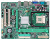
... 2.1 2.2 2.3 2.4 3.1 3.2 4.1 4.2 4.3 4.4 5.1 5.2 5.3 5.4 Before You Start ...3 Package Checklist ...3 Motherboard FeaturesS ...4 Rear Panel Connectors (for Ver 5.x) ...6 Rear Panel Connectors (for Ver 6.x)...6 Motherboard Layout...7 Installing Central Processing Unit (CPU) ...8 Fan Headers ...9 Installing System Memory ...10 Connectors and Slots ...11 How...Headers & Jumpers Setup ...13 Chapter 4: USEFUL HELP ...19 Chapter 5: WarpSpeeder™ ...23 Appendencies: SPEC In Other Language ...32 German ...32 French ...34 Italian ...36 Spanish ...38 Portuguese ...40 Polish ...42 Russian ...44...
... 2.1 2.2 2.3 2.4 3.1 3.2 4.1 4.2 4.3 4.4 5.1 5.2 5.3 5.4 Before You Start ...3 Package Checklist ...3 Motherboard FeaturesS ...4 Rear Panel Connectors (for Ver 5.x) ...6 Rear Panel Connectors (for Ver 6.x)...6 Motherboard Layout...7 Installing Central Processing Unit (CPU) ...8 Fan Headers ...9 Installing System Memory ...10 Connectors and Slots ...11 How...Headers & Jumpers Setup ...13 Chapter 4: USEFUL HELP ...19 Chapter 5: WarpSpeeder™ ...23 Appendencies: SPEC In Other Language ...32 German ...32 French ...34 Italian ...36 Spanish ...38 Portuguese ...40 Polish ...42 Russian ...44...

Setup Manual
Page 17
P4M900-M4 JCMOS1: Clear CMOS Header By placing the jumper on the AC. Set the jumper to "Pin 1-2 close ". Wait for five seconds. Remove AC power line. JSATA1~JSATA2: Serial ATA Connectors The motherboard has a PCI to avoid damaging the motherboard. 1 3 Pin 1-2 Close: Normal Operation (default). 1 3 1 3 Pin 2-3 Close: Clear CMOS data. ※ Clear CMOS Procedures... restore the BIOS safe setting and the CMOS data, please carefully follow the procedures to SATA Controller with 2 channels SATA interface, it satisfies the SATA 1.0 spec and with transfer rate of 1.5Gb/s.
P4M900-M4 JCMOS1: Clear CMOS Header By placing the jumper on the AC. Set the jumper to "Pin 1-2 close ". Wait for five seconds. Remove AC power line. JSATA1~JSATA2: Serial ATA Connectors The motherboard has a PCI to avoid damaging the motherboard. 1 3 Pin 1-2 Close: Normal Operation (default). 1 3 1 3 Pin 2-3 Close: Clear CMOS data. ※ Clear CMOS Procedures... restore the BIOS safe setting and the CMOS data, please carefully follow the procedures to SATA Controller with 2 channels SATA interface, it satisfies the SATA 1.0 spec and with transfer rate of 1.5Gb/s.
Bios Setup
Page 2
... features are supported. P4M900-M4 BIOS Setup Introduction The purpose of CMOS RAM is supplied by this PHEONIX-AWARD BIOS. 1 This system controls most of this manual will to describe the settings in the Pheonix-Award™ BIOS Setup program on this motherboard. Power to CMOS ... Suspend power management modes are implemented via the System Management Interrupt (SMI). BIOS activates at the first stage of the EPA Green PC spec ification. Some additional features, such as keyboard, mouse, serial ports and disk drives. Basic Input-Output System (BIOS) determines what a...
... features are supported. P4M900-M4 BIOS Setup Introduction The purpose of CMOS RAM is supplied by this PHEONIX-AWARD BIOS. 1 This system controls most of this manual will to describe the settings in the Pheonix-Award™ BIOS Setup program on this motherboard. Power to CMOS ... Suspend power management modes are implemented via the System Management Interrupt (SMI). BIOS activates at the first stage of the EPA Green PC spec ification. Some additional features, such as keyboard, mouse, serial ports and disk drives. Basic Input-Output System (BIOS) determines what a...

