
M7VIG 400 user's manual
Page 8
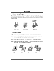
... dot/cut edge should point towards the lever pivot. The white dot/cut edge. Connect the CPU fan power cable to set up a jumper. The illustration shows a 3-pin jumper whose pin 1 and 2 are "close CPU Installation Step1: Pull the lever sideways away from the socket and then raise... the lever up to complete the installation. If no jumper cap is placed on the pins, the jumper is "open Jumper close Pin1-2 close " when jumper cap is completed. Jumper open ". MM77VVIIGG 440000 How to set up Jumper The illustration shows how to the JCFAN1.
... dot/cut edge should point towards the lever pivot. The white dot/cut edge. Connect the CPU fan power cable to set up a jumper. The illustration shows a 3-pin jumper whose pin 1 and 2 are "close CPU Installation Step1: Pull the lever sideways away from the socket and then raise... the lever up to complete the installation. If no jumper cap is placed on the pins, the jumper is "open Jumper close Pin1-2 close " when jumper cap is completed. Jumper open ". MM77VVIIGG 440000 How to set up Jumper The illustration shows how to the JCFAN1.
M7VIG 400 user's manual
Page 12
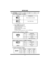
Wait for five seconds. 4. Power on the AC. 6. Set the jumper to "Pin 2-3 Close". 3. CD-ROM Audio-In Header: JCDIN1 Pin Assignment 1 4 JCDIN1 1 Left Channel Input 2 Ground 3 Ground 4 Right Channel Input Digital Audio Connector: JSPDIF1 ... 21 78 1-2 Close 3-4 Close 5-6 Open 133 MHz Open Close Open 166 MHz Open Open Open 10 Set the jumper to "Pin 1-2 Close". 5. Remove AC power line. 2. MM77VVIIGG 440000 JATXPWER1 10 +12V 20 +5V Clear CMOS Jumper: JCMOS1 JCMOS1 1 Pin 1-2 Close 1 Assignment Normal Operation (default) Clear CMOS Data Pin 2-3 Close &#...
Wait for five seconds. 4. Power on the AC. 6. Set the jumper to "Pin 2-3 Close". 3. CD-ROM Audio-In Header: JCDIN1 Pin Assignment 1 4 JCDIN1 1 Left Channel Input 2 Ground 3 Ground 4 Right Channel Input Digital Audio Connector: JSPDIF1 ... 21 78 1-2 Close 3-4 Close 5-6 Open 133 MHz Open Close Open 166 MHz Open Open Open 10 Set the jumper to "Pin 1-2 Close". 5. Remove AC power line. 2. MM77VVIIGG 440000 JATXPWER1 10 +12V 20 +5V Clear CMOS Jumper: JCMOS1 JCMOS1 1 Pin 1-2 Close 1 Assignment Normal Operation (default) Clear CMOS Data Pin 2-3 Close &#...
M7VIG 400 user's manual
Page 27
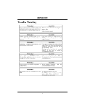
... disk is securely plugged in the standard CMOS setup. * Backing up data and applications files. PROBABLE SOLUTION Cannot boot system after installing second hard * Set master/slave jumpers correctly. Make sure both ends of breaking down firmly until the module spinning. Reformat be read and applications can be booted from CD-ROM...
... disk is securely plugged in the standard CMOS setup. * Backing up data and applications files. PROBABLE SOLUTION Cannot boot system after installing second hard * Set master/slave jumpers correctly. Make sure both ends of breaking down firmly until the module spinning. Reformat be read and applications can be booted from CD-ROM...


