
M7VIG 400 user's manual
Page 4
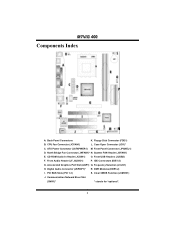
... Audio-In Header (JCDIN1) O. Floppy Disk Connector (FDD1) B. Front Audio Header (JF_AUDIO1) P. IDE Connectors (IDE1-2) G. Communication Network Riser Slot (CNR1)* * stands for "optional". 2 CPU Fan Connector (JCFAN1) L. Front Panel Connector (JPANEL1) D. North Bridge Fan Connector (JNFAN1)* N. Front USB Headers (JUSB2) F. Frequency Selection (JCLK1) H. Digital Audio Connector (JSPDIF1)* R. Case Open Connector (JCI1)* C. System...
... Audio-In Header (JCDIN1) O. Floppy Disk Connector (FDD1) B. Front Audio Header (JF_AUDIO1) P. IDE Connectors (IDE1-2) G. Communication Network Riser Slot (CNR1)* * stands for "optional". 2 CPU Fan Connector (JCFAN1) L. Front Panel Connector (JPANEL1) D. North Bridge Fan Connector (JNFAN1)* N. Front USB Headers (JUSB2) F. Frequency Selection (JCLK1) H. Digital Audio Connector (JSPDIF1)* R. Case Open Connector (JCI1)* C. System...
M7VIG 400 user's manual
Page 8
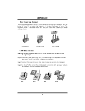
... no jumper cap is placed on these 2 pins. The white dot/cut edge. The CPU will fit only in the correct orientation. Connect the CPU fan power cable to complete the installation. Step1 Step2 Step3 Step4 6 When the Jumper cap is placed on pins, the jumper is "close " when jumper cap... is placed on the CPU and buckle it. Step4: Put the CPU Fan on the pins, the jumper is completed. MM77VVIIGG 440000 How to set up Jumper The illustration shows how to set up to a 90-degree angle...
... no jumper cap is placed on these 2 pins. The white dot/cut edge. The CPU will fit only in the correct orientation. Connect the CPU fan power cable to complete the installation. Step1 Step2 Step3 Step4 6 When the Jumper cap is placed on pins, the jumper is "close " when jumper cap... is placed on the CPU and buckle it. Step4: Put the CPU Fan on the pins, the jumper is completed. MM77VVIIGG 440000 How to set up Jumper The illustration shows how to set up to a 90-degree angle...
M7VIG 400 user's manual
Page 9
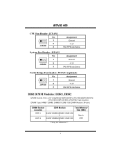
...: JCFAN1 Pin 1 1 2 JCFAN1 3 Assignment Ground +12V FAN RPM rate Sense System Fan Header: JSFAN1 Pin 1 1 2 JSFAN1 3 Assignment Ground +12V FAN RPM rate Sense North Bridge Fan Header: JNFAN1 (optional) Pin Assignment 1 1 Ground 2 JNFAN1 3 +12V FAN RPM rate Sense DDR DIMM Modules: DDR1, DDR2 DRAM Access Time: 2.5V Unbuffered/ DDR 200 MHz (PC1600)/DDR 266 MHz...
...: JCFAN1 Pin 1 1 2 JCFAN1 3 Assignment Ground +12V FAN RPM rate Sense System Fan Header: JSFAN1 Pin 1 1 2 JSFAN1 3 Assignment Ground +12V FAN RPM rate Sense North Bridge Fan Header: JNFAN1 (optional) Pin Assignment 1 1 Ground 2 JNFAN1 3 +12V FAN RPM rate Sense DDR DIMM Modules: DDR1, DDR2 DRAM Access Time: 2.5V Unbuffered/ DDR 200 MHz (PC1600)/DDR 266 MHz...
M7VIG 400 user's manual
Page 17
... panel, you do not need to power up CPU core voltage and Memory voltage. The cool Hardware Monitor smartly indicates the temperatures, voltage and CPU fan speed as well as the chipset information. If you use Windows XP, you can get detail descriptions about BIOS model and chipsets. The Overvoltage Manager...
... panel, you do not need to power up CPU core voltage and Memory voltage. The cool Hardware Monitor smartly indicates the temperatures, voltage and CPU fan speed as well as the chipset information. If you use Windows XP, you can get detail descriptions about BIOS model and chipsets. The Overvoltage Manager...
M7VIG 400 user's manual
Page 27
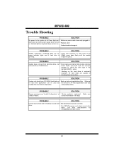
... system after installing second hard * Set master/slave jumpers correctly. Call drive manufacturers for compatibility with other drives. 25 check the drive type in illuminate, fan inside power supply does not on * Replace cable * Contact technical support PROBABLE SOLUTION System inoperative. All hard disks are capable of the power indicator lights...
... system after installing second hard * Set master/slave jumpers correctly. Call drive manufacturers for compatibility with other drives. 25 check the drive type in illuminate, fan inside power supply does not on * Replace cable * Contact technical support PROBABLE SOLUTION System inoperative. All hard disks are capable of the power indicator lights...

