
M7VIG 400 user's manual
Page 4
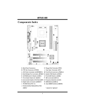
... Connectors (IDE1-2) G. Digital Audio Connector (JSPDIF1)* R. CPU Fan Connector (JCFAN1) L. DDR Modules (DDR1-2) I. Accelerated Graphics Port Slot (AGP1) Q. Front Panel Connector (JPANEL1) D. Frequency Selection (JCLK1) H. Clear CMOS Function (JCMOS1) J. Communication Network Riser Slot (CNR1)* * stands for "optional". 2 Back Panel Connectors K. ATX Power Connector (JATXPWER1) M.
... Connectors (IDE1-2) G. Digital Audio Connector (JSPDIF1)* R. CPU Fan Connector (JCFAN1) L. DDR Modules (DDR1-2) I. Accelerated Graphics Port Slot (AGP1) Q. Front Panel Connector (JPANEL1) D. Frequency Selection (JCLK1) H. Clear CMOS Function (JCMOS1) J. Communication Network Riser Slot (CNR1)* * stands for "optional". 2 Back Panel Connectors K. ATX Power Connector (JATXPWER1) M.
M7VIG 400 user's manual
Page 12
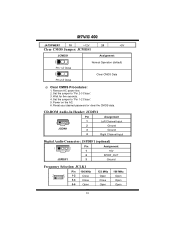
Remove AC power line. 2. Set the jumper to "Pin 1-2 Close". 5. Reset your desired password or clear the CMOS data. Wait for five seconds. 4. CD-ROM Audio-In Header: JCDIN1 Pin Assignment 1 4 JCDIN1 1 Left Channel Input 2 Ground 3 Ground 4 Right Channel Input...MHz Open Close Open 166 MHz Open Open Open 10 Set the jumper to "Pin 2-3 Close". 3. MM77VVIIGG 440000 JATXPWER1 10 +12V 20 +5V Clear CMOS Jumper: JCMOS1 JCMOS1 1 Pin 1-2 Close 1 Assignment Normal Operation (default) Clear CMOS Data Pin 2-3 Close ※ Clear CMOS Procedures: 1. Power on the AC. 6.
Remove AC power line. 2. Set the jumper to "Pin 1-2 Close". 5. Reset your desired password or clear the CMOS data. Wait for five seconds. 4. CD-ROM Audio-In Header: JCDIN1 Pin Assignment 1 4 JCDIN1 1 Left Channel Input 2 Ground 3 Ground 4 Right Channel Input...MHz Open Close Open 166 MHz Open Open Open 10 Set the jumper to "Pin 2-3 Close". 3. MM77VVIIGG 440000 JATXPWER1 10 +12V 20 +5V Clear CMOS Jumper: JCMOS1 JCMOS1 1 Pin 1-2 Close 1 Assignment Normal Operation (default) Clear CMOS Data Pin 2-3 Close ※ Clear CMOS Procedures: 1. Power on the AC. 6.

