Setup Manual
Page 2
Table of Contents Chapter 1: Introduction 1 1.1 Before You Start 1 1.2 Package Checklist 1 1.3 Motherboard Features 2 1.4 Rear Panel Connectors 4 1.5 Motherboard Layout 5 Chapter 2: Hardware Installation 6 2.1 Installing Central Processing Unit (CPU 6 2.2 FAN Headers 8 2.3 Installing System Memory 9 2.4 Connectors and Slots 11 Chapter 3: Headers & Jumpers Setup 14 3.1 How to Setup Jumpers 14 3.2 Detail Settings 14 Chapter 4: RAID Functions ...
Table of Contents Chapter 1: Introduction 1 1.1 Before You Start 1 1.2 Package Checklist 1 1.3 Motherboard Features 2 1.4 Rear Panel Connectors 4 1.5 Motherboard Layout 5 Chapter 2: Hardware Installation 6 2.1 Installing Central Processing Unit (CPU 6 2.2 FAN Headers 8 2.3 Installing System Memory 9 2.4 Connectors and Slots 11 Chapter 3: Headers & Jumpers Setup 14 3.1 How to Setup Jumpers 14 3.2 Detail Settings 14 Chapter 4: RAID Functions ...
Setup Manual
Page 4
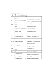
...DDR3 memory module Main Memory Max Memory Capacity 32GB Each DIMM supports 512MB/ Supports DDR3 1066 / 1333 Supports DDR3 1600 (depending on CPU) 1GB/2GB/4GB/8GB DDR3 Registered DIMM and ECC DIMM is not supported SATA 2 & 3 Integrated Serial ATA Controller Data transfer... 2 Motherboard Manual 1.3 MOTHERBOARD FEATURES SPEC Supports Execute Disable Bit / Enhanced Intel Socket 1155 SpeedStep® / Intel Architecture-64 / Extended CPU Intel Core i7 / i5 / i3 / Pentium / Celeron Memory 64 Technology / Virtualization Technology / processor Hyper Threading Chipset Intel H77 IT8728...
...DDR3 memory module Main Memory Max Memory Capacity 32GB Each DIMM supports 512MB/ Supports DDR3 1066 / 1333 Supports DDR3 1600 (depending on CPU) 1GB/2GB/4GB/8GB DDR3 Registered DIMM and ECC DIMM is not supported SATA 2 & 3 Integrated Serial ATA Controller Data transfer... 2 Motherboard Manual 1.3 MOTHERBOARD FEATURES SPEC Supports Execute Disable Bit / Enhanced Intel Socket 1155 SpeedStep® / Intel Architecture-64 / Extended CPU Intel Core i7 / i5 / i3 / Pentium / Celeron Memory 64 Technology / Virtualization Technology / processor Hyper Threading Chipset Intel H77 IT8728...
Setup Manual
Page 5
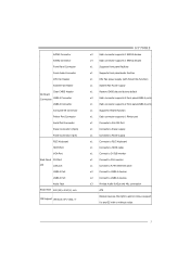
... I/O LAN port USB2.0 Port USB3.0 Port Audio Jack Board Size 220 (W) x 244 (L) mm OS Support Windows XP / Vista / 7 H77MU3 x2 Each connector supports 1 SATA3 devices x4 Each connector supports 1 SATA2 devices x1 Supports front panel facilities x1 Supports front panel audio function x1... CPU Fan power supply (with or without notice 3 connection ATX Biostar reserves the right to add or remove support for any OS with Smart Fan function) x1 System Fan...
... I/O LAN port USB2.0 Port USB3.0 Port Audio Jack Board Size 220 (W) x 244 (L) mm OS Support Windows XP / Vista / 7 H77MU3 x2 Each connector supports 1 SATA3 devices x4 Each connector supports 1 SATA2 devices x1 Supports front panel facilities x1 Supports front panel audio function x1... CPU Fan power supply (with or without notice 3 connection ATX Biostar reserves the right to add or remove support for any OS with Smart Fan function) x1 System Fan...
Setup Manual
Page 8
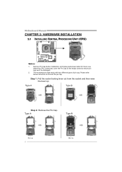
Motherboard Manual CHAPTER 2: HARDWARE INSTALLATION 2.1 INSTALLING CENTRAL PROCESSING UNIT (CPU) Notice: 1. Step 1: Pull the socket locking lever out from the socket and then raise the lever up. Please refer below instruction to ensure pin legs won't be damaged. 2. Step 2: Remove the Pin Cap. 6 When the CPU is removed, cover the Pin Cap on the empty socket to remove the pin cap. Remove Pin Cap before installation, and make good preservation for future use. The motherboard might equip with two different types of pin cap.
Motherboard Manual CHAPTER 2: HARDWARE INSTALLATION 2.1 INSTALLING CENTRAL PROCESSING UNIT (CPU) Notice: 1. Step 1: Pull the socket locking lever out from the socket and then raise the lever up. Please refer below instruction to ensure pin legs won't be damaged. 2. Step 2: Remove the Pin Cap. 6 When the CPU is removed, cover the Pin Cap on the empty socket to remove the pin cap. Remove Pin Cap before installation, and make good preservation for future use. The motherboard might equip with two different types of pin cap.

Setup Manual
Page 9
Connect the CPU FAN power cable into the CPU_FAN1 to complete the installation. Step 4: Hold the CPU down without tilting or sliding the processor in the socket. Step 5: Put the CPU Fan and heatsink assembly on the CPU and buckle it on the retention frame. Lower the processor straight down firmly, and then lower the lever to locked position to complete the installation. 7 Align the notches with your thumb and index fingers, oriented as shown. H77MU3 Step 3: Hold processor with the socket.
Connect the CPU FAN power cable into the CPU_FAN1 to complete the installation. Step 4: Hold the CPU down without tilting or sliding the processor in the socket. Step 5: Put the CPU Fan and heatsink assembly on the CPU and buckle it on the retention frame. Lower the processor straight down firmly, and then lower the lever to locked position to complete the installation. 7 Align the notches with your thumb and index fingers, oriented as shown. H77MU3 Step 3: Hold processor with the socket.
Setup Manual
Page 10
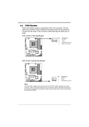
.... Motherboard Manual 2.2 FAN HEADERS These fan headers support cooling-fans built in the computer. The fan cable and connector may be connected to GND. 8 CPU_FAN1: CPU Fan Header Pin Assignment 1 Ground 2 +12V 1 4 3 FAN RPM rate sense 4 Smart Fan Control SYS_FAN1: System Fan Header Pin 1 2 13 3 Assignment Ground +12V FAN RPM rate...
.... Motherboard Manual 2.2 FAN HEADERS These fan headers support cooling-fans built in the computer. The fan cable and connector may be connected to GND. 8 CPU_FAN1: CPU Fan Header Pin Assignment 1 Ground 2 +12V 1 4 3 FAN RPM rate sense 4 Smart Fan Control SYS_FAN1: System Fan Header Pin 1 2 13 3 Assignment Ground +12V FAN RPM rate...
Setup Manual
Page 14
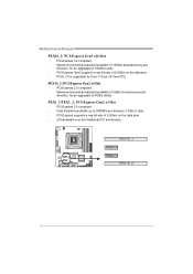
.../s simultaneously per direction; 1GB/s in total. - PEX1_1/PEX1_2: PCI-Express Gen2 x1 Slot - PCI-Express 3.0 compliant. - PCI-E 3.0 is supported by Core i7-3xxx / i5-3xxx CPU. PEX16_1 PEX1_1 PEX1_2 PEX16_2 12 PEX16_2: PCI-Express Gen2 x4 Slot -
.../s simultaneously per direction; 1GB/s in total. - PEX1_1/PEX1_2: PCI-Express Gen2 x1 Slot - PCI-Express 3.0 compliant. - PCI-E 3.0 is supported by Core i7-3xxx / i5-3xxx CPU. PEX16_1 PEX1_1 PEX1_2 PEX16_2 12 PEX16_2: PCI-Express Gen2 x4 Slot -

Setup Manual
Page 15
H77MU3 ATXPWR1: ATX Power Source Connector This connector allows user to connect 24-pin power connector on the system, please make sure that ATXPWR1 and ATXPWR2 ... 3 Ground 4 +5V 5 Ground 6 +5V 7 Ground 8 PW_OK 9 Standby Voltage+5V 10 +12V 11 +12V 12 +3.3V ATXPWR2: ATX Power Source Connector This connector provides +12V to CPU power circuit.
H77MU3 ATXPWR1: ATX Power Source Connector This connector allows user to connect 24-pin power connector on the system, please make sure that ATXPWR1 and ATXPWR2 ... 3 Ground 4 +5V 5 Ground 6 +5V 7 Ground 8 PW_OK 9 Standby Voltage+5V 10 +12V 11 +12V 12 +3.3V ATXPWR2: ATX Power Source Connector This connector provides +12V to CPU power circuit.
Setup Manual
Page 24
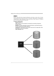
... and Benefits Drives: Minimum 3. Uses: RAID 5 is placed on a different drive from those used to store the data itself. Write performance can be CPU intensive. Fault Tolerance: Yes. It writes data and parity blocks across three or more drives.
... and Benefits Drives: Minimum 3. Uses: RAID 5 is placed on a different drive from those used to store the data itself. Write performance can be CPU intensive. Fault Tolerance: Yes. It writes data and parity blocks across three or more drives.
Setup Manual
Page 27
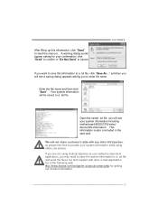
...cancel. Open the saved .txt file, you will see your system information including motherboard/BIOS/CPU/video/ device/OS information. We will be saved to a .txt file. A warning ...our contact information. 25 click "Send" to confirm or "Do Not Send" to the following web http://www.biostar.com.tw/app/en-us/about/contact.php for your default e-mail client application, you want to save the...to a .txt file, click "Save As..." This information is also concluded in the sent mail. H77MU3 If you may need to save this information, click "Send" to send the mail out. Enter the file name...
...cancel. Open the saved .txt file, you will see your system information including motherboard/BIOS/CPU/video/ device/OS information. We will be saved to a .txt file. A warning ...our contact information. 25 click "Send" to confirm or "Do Not Send" to the following web http://www.biostar.com.tw/app/en-us/about/contact.php for your default e-mail client application, you want to save the...to a .txt file, click "Save As..." This information is also concluded in the sent mail. H77MU3 If you may need to save this information, click "Send" to send the mail out. Enter the file name...
Setup Manual
Page 30
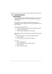
... Clear the CMOS data. (See "Close CMOS Header: JCMOS1" section) 2. Power on the system again. 28 The CPU cooler surface is placed evenly with the CPU speed. Remove the power cord from power supply for seconds. 3. Plug in the power cord and boot up the system.... Wait for seconds. 2. Wait for seconds, the phenomenon means the CPU protection function has been activated. CPU fan speed is fulfilling with the CPU surface. 2. Motherboard Manual 5.3 EXTRA INFORMATION CPU Overheated If the system shuts down automatically after system is powered on for seconds. 3. ...
... Clear the CMOS data. (See "Close CMOS Header: JCMOS1" section) 2. Power on the system again. 28 The CPU cooler surface is placed evenly with the CPU speed. Remove the power cord from power supply for seconds. 3. Plug in the power cord and boot up the system.... Wait for seconds. 2. Wait for seconds, the phenomenon means the CPU protection function has been activated. CPU fan speed is fulfilling with the CPU surface. 2. Motherboard Manual 5.3 EXTRA INFORMATION CPU Overheated If the system shuts down automatically after system is powered on for seconds. 3. ...
Setup Manual
Page 50
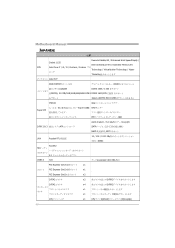
... JAPANESE 仕様 Execute Disable Bit / Enhanced Intel SpeedStep® / Socket 1155 Intel Architecture-64 / Extended Memory 64 CPU Intel Core i7 / i5 / i3 / Pentium / Celeron プロ Technology / Virtualization Technology / Hyper セッサ...Threading Intel H77 DDR3 DIMM x 4 DDR3 32GB DDR3 1066 / 1333 各DIMMは 512MB/1GB/2GB/4GB/8GB DDR3 DDR3 1600(CPU 登録済みDIMMとECC DIMM IT8728 Super I/O Super I/O機 H/Wモニター ITE SATA 2 & 3...
... JAPANESE 仕様 Execute Disable Bit / Enhanced Intel SpeedStep® / Socket 1155 Intel Architecture-64 / Extended Memory 64 CPU Intel Core i7 / i5 / i3 / Pentium / Celeron プロ Technology / Virtualization Technology / Hyper セッサ...Threading Intel H77 DDR3 DIMM x 4 DDR3 32GB DDR3 1066 / 1333 各DIMMは 512MB/1GB/2GB/4GB/8GB DDR3 DDR3 1600(CPU 登録済みDIMMとECC DIMM IT8728 Super I/O Super I/O機 H/Wモニター ITE SATA 2 & 3...

Bios Manual
Page 3
..., and this user's manual and any settings, please load the default settings to enter the UEFI BIOS setup utility. H77MU3 UEFI BIOS Manual Supported CPUs This AMI UEFI BIOS supports the Intel CPU. Notice z The default UEFI BIOS settings apply for your reference only. Use Load Setup Default under the Exit Menu...
..., and this user's manual and any settings, please load the default settings to enter the UEFI BIOS setup utility. H77MU3 UEFI BIOS Manual Supported CPUs This AMI UEFI BIOS supports the Intel CPU. Notice z The default UEFI BIOS settings apply for your reference only. Use Load Setup Default under the Exit Menu...

Bios Manual
Page 5
PCI Subsystem Settings 4 Notice z Beware of that setting inappropriate values in items of this menu may cause system to configure the settings of CPU, Super I/O, Power Management, and other system devices. H77MU3 UEFI BIOS Manual 2 Advanced Menu The Advanced Menu allows you to malfunction.
PCI Subsystem Settings 4 Notice z Beware of that setting inappropriate values in items of this menu may cause system to configure the settings of CPU, Super I/O, Power Management, and other system devices. H77MU3 UEFI BIOS Manual 2 Advanced Menu The Advanced Menu allows you to malfunction.
Bios Manual
Page 9
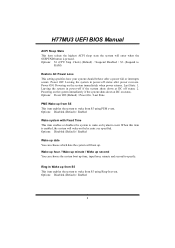
Options: S1 (CPU Stop Clock) (Default) / Suspend Disabled / S3 (Suspend to RAM) Restore AC Power Loss This setting specifies how your system should behave after power recovers. Options: ... date You can choose the system boot up time, input hour, minute and second to wake from S5 using PEM event. Options: Disabled (Default) / Enabled 8 H77MU3 UEFI BIOS Manual ACPI Sleep State This item selects the highest ACPI sleep state the system will enter when the SUSPEND button is enabled, the...
Options: S1 (CPU Stop Clock) (Default) / Suspend Disabled / S3 (Suspend to RAM) Restore AC Power Loss This setting specifies how your system should behave after power recovers. Options: ... date You can choose the system boot up time, input hour, minute and second to wake from S5 using PEM event. Options: Disabled (Default) / Enabled 8 H77MU3 UEFI BIOS Manual ACPI Sleep State This item selects the highest ACPI sleep state the system will enter when the SUSPEND button is enabled, the...

Bios Manual
Page 10
... on function. Options: Disabled (Default) / Enabled USB Device Wakeup from S3/S4 This item allows you to set Specific key. Options: Disabled (Default) / Enabled CPU Configuration 9 H77MU3 UEFI BIOS Manual PS2 Keyboard PowerOn This item allows you to control the keyboard power on function. Options: Disabled (Default) / Any Key / Stroke Key / Specific...
... on function. Options: Disabled (Default) / Enabled USB Device Wakeup from S3/S4 This item allows you to set Specific key. Options: Disabled (Default) / Enabled CPU Configuration 9 H77MU3 UEFI BIOS Manual PS2 Keyboard PowerOn This item allows you to control the keyboard power on function. Options: Disabled (Default) / Any Key / Stroke Key / Specific...
Bios Manual
Page 18
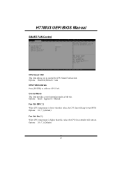
... provides several operation modes of the fan. Options: 20 (℃) (Default) 17 Options: Disabled (Default) / Auto CPU FAN Calibrate Press [ENTER] to control the CPU Smart Fan function. H77MU3 UEFI BIOS Manual SMART FAN Control CPU Smart FAN This item allows you to calibrate CPU FAN. Options: Quiet / Aggressive / Manual Fan Ctrl OFF(℃) When...
... provides several operation modes of the fan. Options: 20 (℃) (Default) 17 Options: Disabled (Default) / Auto CPU FAN Calibrate Press [ENTER] to control the CPU Smart Fan function. H77MU3 UEFI BIOS Manual SMART FAN Control CPU Smart FAN This item allows you to calibrate CPU FAN. Options: Quiet / Aggressive / Manual Fan Ctrl OFF(℃) When...
Bios Manual
Page 19
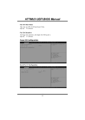
H77MU3 UEFI BIOS Manual Fan Ctrl Start Value This item sets CPU FAN Start Speed Value. Options: 30 (Default) Super IO Configuration Serial Port 0 Configuration 18 Options: 50 (Default) Fan Ctrl Sensitive The bigger the numeral is, the higher the FAN speed is.
H77MU3 UEFI BIOS Manual Fan Ctrl Start Value This item sets CPU FAN Start Speed Value. Options: 30 (Default) Super IO Configuration Serial Port 0 Configuration 18 Options: 50 (Default) Fan Ctrl Sensitive The bigger the numeral is, the higher the FAN speed is.

Bios Manual
Page 22
H77MU3 UEFI BIOS Manual Shutdown Temperature This item allows you to set up the CPU shutdown Temperature. Options: Disabled (Default) / 70℃/158℉ / 75℃/167℉ / 80℃/176℉ / 85℃/185℉ / 90℃/194℉ 21
H77MU3 UEFI BIOS Manual Shutdown Temperature This item allows you to set up the CPU shutdown Temperature. Options: Disabled (Default) / 70℃/158℉ / 75℃/167℉ / 80℃/176℉ / 85℃/185℉ / 90℃/194℉ 21

Bios Manual
Page 23
H77MU3 UEFI BIOS Manual 3 Chipset Menu This section describes configuring the PCI bus system. PCH-IO Configuration 22 Notice z Beware of that setting inappropriate values in items of the CPU itself uses when communicating with its own special components. PCI, or Personal Computer Interconnect, is a system which allows I/O devices to operate at speeds nearing the speed of this menu may cause system to malfunction.
H77MU3 UEFI BIOS Manual 3 Chipset Menu This section describes configuring the PCI bus system. PCH-IO Configuration 22 Notice z Beware of that setting inappropriate values in items of the CPU itself uses when communicating with its own special components. PCI, or Personal Computer Interconnect, is a system which allows I/O devices to operate at speeds nearing the speed of this menu may cause system to malfunction.


