Update Manual
Page 3
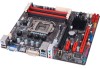
...while updating the BIOS will lead to flash the BIOS file. For better performance, the software is completed, asking you to restart the system. BIOSTAR BIOS flasher BIOSTAR BIOS Flasher is a BIOS flashing utility providing you an easy and simple way to update your reference only. Then, copy and save the ... board may be changed without notice. Select the proper BIOS file, and a message asking if you are subject to be slightly different from this manual. While the system boots up and the full screen logo shows up . Go to the website to enter BIOS setup. After entering the POST ...
...while updating the BIOS will lead to flash the BIOS file. For better performance, the software is completed, asking you to restart the system. BIOSTAR BIOS flasher BIOSTAR BIOS Flasher is a BIOS flashing utility providing you an easy and simple way to update your reference only. Then, copy and save the ... board may be changed without notice. Select the proper BIOS file, and a message asking if you are subject to be slightly different from this manual. While the system boots up and the full screen logo shows up . Go to the website to enter BIOS setup. After entering the POST ...
Setup Manual
Page 1
...to the contents here and specially disclaims any implied warranties of merchantability or fitness for any purpose. H77MU3 Setup Manual FCC Information and Copyright This equipment has been tested and found in this user's manual. Dichiarazione di conformità sintetica Ai sensi dell'art. 2 comma 3 del D.M. 275 ... trademarks of a Class B digital device, pursuant to radio communications. Further the vendor reserves the right to revise this user's manual is not allowed without obligation to provide reasonable protection against harmful interference in a residential installation.
...to the contents here and specially disclaims any implied warranties of merchantability or fitness for any purpose. H77MU3 Setup Manual FCC Information and Copyright This equipment has been tested and found in this user's manual. Dichiarazione di conformità sintetica Ai sensi dell'art. 2 comma 3 del D.M. 275 ... trademarks of a Class B digital device, pursuant to radio communications. Further the vendor reserves the right to revise this user's manual is not allowed without obligation to provide reasonable protection against harmful interference in a residential installation.
Setup Manual
Page 3
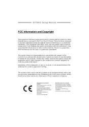
Loose parts will cause short circuits which may be 0 to area or your motherboard version. 1 CHAPTER 1: INTRODUCTION H77MU3 1.1 BEFORE YOU START Thank you take the motherboard out from anti-static bag, ground yourself properly by touching any unfastened ...and stable working environment with sufficient lighting. „ Always disconnect the computer from power outlet before operation. „ Before you for ATX Case X 1 User's Manual X 1 Fully Setup Driver DVD X 1 Note: The package contents may damage the equipment. „ Keep the computer from dangerous area, such as heat source,...
Loose parts will cause short circuits which may be 0 to area or your motherboard version. 1 CHAPTER 1: INTRODUCTION H77MU3 1.1 BEFORE YOU START Thank you take the motherboard out from anti-static bag, ground yourself properly by touching any unfastened ...and stable working environment with sufficient lighting. „ Always disconnect the computer from power outlet before operation. „ Before you for ATX Case X 1 User's Manual X 1 Fully Setup Driver DVD X 1 Note: The package contents may damage the equipment. „ Keep the computer from dangerous area, such as heat source,...
Setup Manual
Page 4
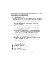
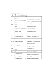
Motherboard Manual 1.3 MOTHERBOARD FEATURES SPEC Supports Execute Disable Bit / Enhanced Intel Socket 1155 SpeedStep® / Intel Architecture-64 / Extended CPU Intel Core i7 / i5 / i3 / Pentium / Celeron ...
Motherboard Manual 1.3 MOTHERBOARD FEATURES SPEC Supports Execute Disable Bit / Enhanced Intel Socket 1155 SpeedStep® / Intel Architecture-64 / Extended CPU Intel Core i7 / i5 / i3 / Pentium / Celeron ...
Setup Manual
Page 6
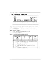
... = Single Pipe Single Display With One Display Device Disabled z X = Unsupported / Note Applicable 4 NOTE: Maximum resolution: HDMI: 1920 x 1200 @60Hz, compliant with USB2.0/USB1.X devices. Motherboard Manual 1.4 REAR PANEL CONNECTORS PS /2 Keyboard / Mouse US B2 .0X 2 VGA HDMI DVI-D LAN USB 3 .0X 2 Line In/ Surround Line Out Mic In 1/ Bass/ Center NOTE...
... = Single Pipe Single Display With One Display Device Disabled z X = Unsupported / Note Applicable 4 NOTE: Maximum resolution: HDMI: 1920 x 1200 @60Hz, compliant with USB2.0/USB1.X devices. Motherboard Manual 1.4 REAR PANEL CONNECTORS PS /2 Keyboard / Mouse US B2 .0X 2 VGA HDMI DVI-D LAN USB 3 .0X 2 Line In/ Surround Line Out Mic In 1/ Bass/ Center NOTE...
Setup Manual
Page 8
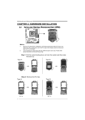
Please refer below instruction to ensure pin legs won't be damaged. 2. Remove Pin Cap before installation, and make good preservation for future use. Step 1: Pull the socket locking lever out from the socket and then raise the lever up. Motherboard Manual CHAPTER 2: HARDWARE INSTALLATION 2.1 INSTALLING CENTRAL PROCESSING UNIT (CPU) Notice: 1. The motherboard might equip with two different types of pin cap. When the CPU is removed, cover the Pin Cap on the empty socket to remove the pin cap. Step 2: Remove the Pin Cap. 6
Please refer below instruction to ensure pin legs won't be damaged. 2. Remove Pin Cap before installation, and make good preservation for future use. Step 1: Pull the socket locking lever out from the socket and then raise the lever up. Motherboard Manual CHAPTER 2: HARDWARE INSTALLATION 2.1 INSTALLING CENTRAL PROCESSING UNIT (CPU) Notice: 1. The motherboard might equip with two different types of pin cap. When the CPU is removed, cover the Pin Cap on the empty socket to remove the pin cap. Step 2: Remove the Pin Cap. 6
Setup Manual
Page 10
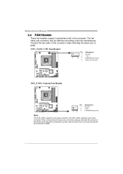
... sense 4 Smart Fan Control SYS_FAN1: System Fan Header Pin 1 2 13 3 Assignment Ground +12V FAN RPM rate sense Note: The SYS_FAN1 supports 3-pin head connector; Motherboard Manual 2.2 FAN HEADERS These fan headers support cooling-fans built in the computer. When connecting with wires onto connectors, please note that the red wire is...
... sense 4 Smart Fan Control SYS_FAN1: System Fan Header Pin 1 2 13 3 Assignment Ground +12V FAN RPM rate sense Note: The SYS_FAN1 supports 3-pin head connector; Motherboard Manual 2.2 FAN HEADERS These fan headers support cooling-fans built in the computer. When connecting with wires onto connectors, please note that the red wire is...
Setup Manual
Page 12
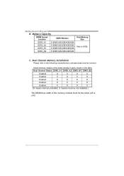
... X O X O Enabled O O O O Enabled O X X O Enabled X O O X (O means memory installed, X means memory not installed.) The DRAM bus width of the same density in pairs, shown in the table. C. Motherboard Manual B. Dual Channel Memory Installation Please refer to the following requirements to activate Dual Channel function: Install memory module of the memory module must be the...
... X O X O Enabled O O O O Enabled O X X O Enabled X O O X (O means memory installed, X means memory not installed.) The DRAM bus width of the same density in pairs, shown in the table. C. Motherboard Manual B. Dual Channel Memory Installation Please refer to the following requirements to activate Dual Channel function: Install memory module of the memory module must be the...
Setup Manual
Page 14
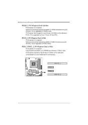
Motherboard Manual PEX16_1: PCI-Express Gen3 x16 Slot - PEX16_2: PCI-Express Gen2 x4 Slot - PEX1_1/PEX1_2: PCI-Express Gen2 x1 Slot - PCI-Express 2.0 compliant. - PCI-Express 2.0 compliant. - ...
Motherboard Manual PEX16_1: PCI-Express Gen3 x16 Slot - PEX16_2: PCI-Express Gen2 x4 Slot - PEX1_1/PEX1_2: PCI-Express Gen2 x1 Slot - PCI-Express 2.0 compliant. - PCI-Express 2.0 compliant. - ...
Setup Manual
Page 16
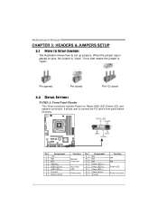
... closed Pin1-2 closed 3.2 DETAIL SETTINGS PANEL1: Front Panel Header This 16-pin connector includes Power-on, Reset, HDD LED, Power LED, and speaker connection. Motherboard Manual CHAPTER 3: HEADERS & JUMPERS SETUP 3.1 HOW TO SETUP JUMPERS The illustration shows how to connect the PC case's front panel switch functions.
... closed Pin1-2 closed 3.2 DETAIL SETTINGS PANEL1: Front Panel Header This 16-pin connector includes Power-on, Reset, HDD LED, Power LED, and speaker connection. Motherboard Manual CHAPTER 3: HEADERS & JUMPERS SETUP 3.1 HOW TO SETUP JUMPERS The illustration shows how to connect the PC case's front panel switch functions.
Setup Manual
Page 18
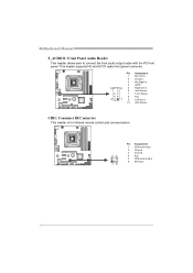
Pin Assignment 1 Mic Left in 2 Ground 3 Mic Right in 4 GPIO 10 9 5 Right line in 6 Jack Sense 7 Front Sense 8 Key 2 1 9 Left line in 10 Jack Sense CIR1: Consumer IR Connector This header is for infrared remote control and communication. 26 15 Pin Assignment 1 IrDA serial input 2 Ground 3 Ground 4 Key 5 IrDA serial output 6 IR Power 16 Motherboard Manual F_AUDIO1: Front Panel Audio Header This header allows user to connect the front audio output cable with the PC front panel. This header supports HD and AC'97 audio front panel connector.
Pin Assignment 1 Mic Left in 2 Ground 3 Mic Right in 4 GPIO 10 9 5 Right line in 6 Jack Sense 7 Front Sense 8 Key 2 1 9 Left line in 10 Jack Sense CIR1: Consumer IR Connector This header is for infrared remote control and communication. 26 15 Pin Assignment 1 IrDA serial input 2 Ground 3 Ground 4 Key 5 IrDA serial output 6 IR Power 16 Motherboard Manual F_AUDIO1: Front Panel Audio Header This header allows user to connect the front audio output cable with the PC front panel. This header supports HD and AC'97 audio front panel connector.
Setup Manual
Page 20
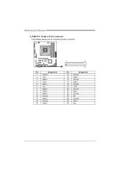
Motherboard Manual J_PRINT1: Printer Port Connector This header allows you to connector printer on the PC. Pin Assignment 1 -Strobe 2 -ALF 3 Data 0 4 -Error 5 Data 1 6 -Init 7 Data 2 8 -Scltin 9 Data 3 10 Ground 11 Data 4 12 Ground 13 Data 5 2 26 1 25 Pin Assignment 14 Ground 15 Data 6 16 Ground 17 Data 7 18 Ground 19 -ACK 20 Ground 21 Busy 22 Ground 23 PE 24 Ground 25 SCLT 26 Key 18
Motherboard Manual J_PRINT1: Printer Port Connector This header allows you to connector printer on the PC. Pin Assignment 1 -Strobe 2 -ALF 3 Data 0 4 -Error 5 Data 1 6 -Init 7 Data 2 8 -Scltin 9 Data 3 10 Ground 11 Data 4 12 Ground 13 Data 5 2 26 1 25 Pin Assignment 14 Ground 15 Data 6 16 Ground 17 Data 7 18 Ground 19 -ACK 20 Ground 21 Busy 22 Ground 23 PE 24 Ground 25 SCLT 26 Key 18
Setup Manual
Page 22
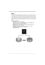
... 1 provides a hot-standby copy of data if the active volume or drive is actually carried out in parallel across 2 disk drives in the array. Motherboard Manual RAID 1: Every read and write is corrupted or becomes unavailable because of a hardware failure. RAID techniques can reside on the same disk or on a second... redundancy. Performance is ideal for high-availability solutions, or as a form of one drive fail, the controller switches to the other application that eliminates tedious manual backups to more expensive and less reliable media.
... 1 provides a hot-standby copy of data if the active volume or drive is actually carried out in parallel across 2 disk drives in the array. Motherboard Manual RAID 1: Every read and write is corrupted or becomes unavailable because of a hardware failure. RAID techniques can reside on the same disk or on a second... redundancy. Performance is ideal for high-availability solutions, or as a form of one drive fail, the controller switches to the other application that eliminates tedious manual backups to more expensive and less reliable media.
Setup Manual
Page 24
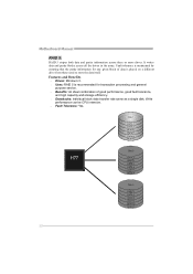
... 1 DATA 1 DATA 3 PARITY DATA 7 DATA 9 PARITY Disk 2 DATA 2 PARITY DATA 5 DATA 8 PARITY DATA 11 Disk 3 PARITY DATA 4 DATA 6 PARITY DATA 10 DATA 12 22 Motherboard Manual RAID 5: RAID 5 stripes both data and parity information across all the drives in the array.
... 1 DATA 1 DATA 3 PARITY DATA 7 DATA 9 PARITY Disk 2 DATA 2 PARITY DATA 5 DATA 8 PARITY DATA 11 Disk 3 PARITY DATA 4 DATA 6 PARITY DATA 10 DATA 12 22 Motherboard Manual RAID 5: RAID 5 stripes both data and parity information across all the drives in the array.
Setup Manual
Page 25
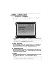
... from http://get.adobe.com/reader/ 23 Please download the latest version of Acrobat Reader software from the paperback manual, we also provide manual in the Driver CD. C. Note: If this window didn't show up after you installed your operating system, please insert the Fully... Setup Driver CD into your optical drive and install the driver for your motherboard and operating system. CHAPTER 5: USEFUL HELP H77MU3 5.1 DRIVER INSTALLATION ...
... from http://get.adobe.com/reader/ 23 Please download the latest version of Acrobat Reader software from the paperback manual, we also provide manual in the Driver CD. C. Note: If this window didn't show up after you installed your operating system, please insert the Fully... Setup Driver CD into your optical drive and install the driver for your motherboard and operating system. CHAPTER 5: USEFUL HELP H77MU3 5.1 DRIVER INSTALLATION ...
Setup Manual
Page 26
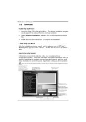
... would like to send the copy to help you must provide. Before you use this information, you to contact with our Tech-Support system. Motherboard Manual 5.2 SOFTWARE Installing Software 1. Provide the name of your system. *Select your default e-mail clientapplication program. *represents important informa ti on of the power suppl y manufacturer...
... would like to send the copy to help you must provide. Before you use this information, you to contact with our Tech-Support system. Motherboard Manual 5.2 SOFTWARE Installing Software 1. Provide the name of your system. *Select your default e-mail clientapplication program. *represents important informa ti on of the power suppl y manufacturer...
Setup Manual
Page 28
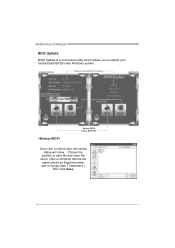
Choose the position to a .bin file Update BIOS with a BIOS file Once click on this button, the saving dialog will show. AWARD BIOS Show current BIOS information AMI BIOS Clear CMOS function (Only for AWARD BIOS) Save current BIOS to save file and enter file name. (We recommend that the file name should be English/number and no longer than 7 characters.) Then click Save. 26 Motherboard Manual BIOS Update BIOS Update is a convenient utility which allows you to update your motherboard BIOS under Windows system.
Choose the position to a .bin file Update BIOS with a BIOS file Once click on this button, the saving dialog will show. AWARD BIOS Show current BIOS information AMI BIOS Clear CMOS function (Only for AWARD BIOS) Save current BIOS to save file and enter file name. (We recommend that the file name should be English/number and no longer than 7 characters.) Then click Save. 26 Motherboard Manual BIOS Update BIOS Update is a convenient utility which allows you to update your motherboard BIOS under Windows system.
Setup Manual
Page 29
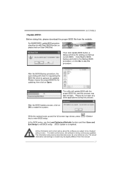
... for updating, then click on board may take minutes. After the BIOS Update process, click on Clear CMOS first. H77MU3 Before doing this, please download the proper BIOS file from this manual. 27 or click No to skip this process may be changed without notice. The utility will show for requesting the...
... for updating, then click on board may take minutes. After the BIOS Update process, click on Clear CMOS first. H77MU3 Before doing this, please download the proper BIOS file from this manual. 27 or click No to skip this process may be changed without notice. The utility will show for requesting the...
Setup Manual
Page 30
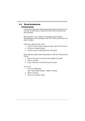
... you can: 1. Power on the system again. 28 In this case, please double check: 1. Plug in the power cord and boot up the system. Motherboard Manual 5.3 EXTRA INFORMATION CPU Overheated If the system shuts down automatically after system is over heated, the motherboard will shutdown automatically to relief the CPU protection...
... you can: 1. Power on the system again. 28 In this case, please double check: 1. Plug in the power cord and boot up the system. Motherboard Manual 5.3 EXTRA INFORMATION CPU Overheated If the system shuts down automatically after system is over heated, the motherboard will shutdown automatically to relief the CPU protection...
Setup Manual
Page 32
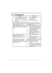
... , power indicator lights are on keyboard does not shine. Make sure both ends of the power supply does not 2. check the drive type in . Motherboard Manual 5.5 TROUBLESHOOTING Probable Solution 1. System only boots from a hard disk 1. System cannot boot after user installs a 1. Contact technical support. 2. System does not boot from an optical...
... , power indicator lights are on keyboard does not shine. Make sure both ends of the power supply does not 2. check the drive type in . Motherboard Manual 5.5 TROUBLESHOOTING Probable Solution 1. System only boots from a hard disk 1. System cannot boot after user installs a 1. Contact technical support. 2. System does not boot from an optical...

