
Manual
Page 5
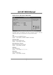
Select a device and press to enter the sub-menu of floppy disk drive installed in / None IDE Configuration T he BIOS will automatically detect the presence of ID E/SAT A devices. ATA/IDE Configuration T his item allows you to "Compatible". Options: ... Pri, PA TA Sec] [ Disabled] [ 35] Options Disa bled Comp atible Enha nced S elect Screen S elect Item En terG o to control the onboard IDE controller. G41-M 7 BIOS Manual Floppy A Select the type of detailed options. Options: Befo re PATA (Default) / Behind PAT A Legacy IDE Channels T his item allows you to Sub...
Select a device and press to enter the sub-menu of floppy disk drive installed in / None IDE Configuration T he BIOS will automatically detect the presence of ID E/SAT A devices. ATA/IDE Configuration T his item allows you to "Compatible". Options: ... Pri, PA TA Sec] [ Disabled] [ 35] Options Disa bled Comp atible Enha nced S elect Screen S elect Item En terG o to control the onboard IDE controller. G41-M 7 BIOS Manual Floppy A Select the type of detailed options. Options: Befo re PATA (Default) / Behind PAT A Legacy IDE Channels T his item allows you to Sub...
Manual
Page 6
...type of the sub-menu. Options: Auto (Default) / 0 / 1 / 2 / 3 / 4 DMA Mode Select the DMA mode. Options: Auto (Default) / Disabled 5 G41-M 7 BIOS Manual SATA1/2 Dev ice; C hange Option F1 G eneral Help F10 S ave and Exit ESC E xit vxx .xx (C)Copyright 1985-200x, American Me gatrends, Inc....] Select the type of device connected to the name of the IDE/SAT A drive. Options: Auto (Default) / CD/DVD / ARMD / Not Installed LBA/Large Mode Enable or disable the LBA mode. Options: Auto (Default) / Disabled Block (Multi-Sector Transfer) Enable or disable multi-sector trans fer.
...type of the sub-menu. Options: Auto (Default) / 0 / 1 / 2 / 3 / 4 DMA Mode Select the DMA mode. Options: Auto (Default) / Disabled 5 G41-M 7 BIOS Manual SATA1/2 Dev ice; C hange Option F1 G eneral Help F10 S ave and Exit ESC E xit vxx .xx (C)Copyright 1985-200x, American Me gatrends, Inc....] Select the type of device connected to the name of the IDE/SAT A drive. Options: Auto (Default) / CD/DVD / ARMD / Not Installed LBA/Large Mode Enable or disable the LBA mode. Options: Auto (Default) / Disabled Block (Multi-Sector Transfer) Enable or disable multi-sector trans fer.

Manual
Page 10
...Options: 378 (Default) / 278 / 3BC / Disabled Parallel Port M ode T his item allows multi-processing fun ction for multi-core processors. G41-M 7 BIOS Manual Core Multi-Processing T his item allows you to determine how the parallel port should function. ECP+EPP Using Parallel port as Standard... Printer Port. Onboard Floppy Controller Select enabled if your system has a floppy disk controller (FDC) installed on AC Powe r Loss [ Enabled] [ 378] [ Normal] [ IRQ7] [ Disabled] [ Disabled] [ Power Off] Allo ws BIOS to use it....
...Options: 378 (Default) / 278 / 3BC / Disabled Parallel Port M ode T his item allows multi-processing fun ction for multi-core processors. G41-M 7 BIOS Manual Core Multi-Processing T his item allows you to determine how the parallel port should function. ECP+EPP Using Parallel port as Standard... Printer Port. Onboard Floppy Controller Select enabled if your system has a floppy disk controller (FDC) installed on AC Powe r Loss [ Enabled] [ 378] [ Normal] [ IRQ7] [ Disabled] [ Disabled] [ Power Off] Allo ws BIOS to use it....
Manual
Page 21
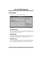
.... You can also change the booting sequence. T he number of device items that appears on the screen depends on the number of devices installed in the system. Hard Disk Drives T he BIOS will attempt to arrange the removable drive boot sequence automatically. You can also ch ange ... Settings > Boot Device Priority > Hard Disk Dr ives > Removable Dr ives > CD/DVD Drive s > Boot Setting s Configuration Specifies the Boot Device Priority sequence. G41-M 7 BIOS Manual 4 Boot Menu T his menu allows you to Sub Screen F1 G eneral Help F10 S ave and Exit ESC E xit vxx .xx (C)Copyright ...
.... You can also change the booting sequence. T he number of device items that appears on the screen depends on the number of devices installed in the system. Hard Disk Drives T he BIOS will attempt to arrange the removable drive boot sequence automatically. You can also ch ange ... Settings > Boot Device Priority > Hard Disk Dr ives > Removable Dr ives > CD/DVD Drive s > Boot Setting s Configuration Specifies the Boot Device Priority sequence. G41-M 7 BIOS Manual 4 Boot Menu T his menu allows you to Sub Screen F1 G eneral Help F10 S ave and Exit ESC E xit vxx .xx (C)Copyright ...

Manual
Page 22
Options: Force BIOS (Default) / Keep Current 21 G41-M 7 BIOS Manual CD/DV D Drives T he syst em. You can also change the booting sequence. Boot Settings Configuration BIOS S ETUP UTILITY Boot Boot Settings Conf ....xx (C)C opyright 198 5-200x, Amer ican Megatre nds, Inc. The number of device items that appears on the screen depends on the number of devices installed in the system. S elect Screen S elect Item +-
Options: Force BIOS (Default) / Keep Current 21 G41-M 7 BIOS Manual CD/DV D Drives T he syst em. You can also change the booting sequence. Boot Settings Configuration BIOS S ETUP UTILITY Boot Boot Settings Conf ....xx (C)C opyright 198 5-200x, Amer ican Megatre nds, Inc. The number of device items that appears on the screen depends on the number of devices installed in the system. S elect Screen S elect Item +-

Manual
Page 24
G41-M 7 BIOS Manual 5 Chipset Menu T his chipset manage bus speeds and access to malfunction. Main Advan ced BIOS SETU P U TILITY PCIPnP Boot Chipset Performance Exit Advanced Chips et Settings WARNING: Setti ng wrong values in items of the chipset installed on your system. Notice z Beware of that setting inappropriate values in below sections...
G41-M 7 BIOS Manual 5 Chipset Menu T his chipset manage bus speeds and access to malfunction. Main Advan ced BIOS SETU P U TILITY PCIPnP Boot Chipset Performance Exit Advanced Chips et Settings WARNING: Setti ng wrong values in items of the chipset installed on your system. Notice z Beware of that setting inappropriate values in below sections...
Manual
Page 34
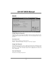
... view configurations but will be able to provide/revise supervisor and user password. BIOS SETU P U TILITY Exit Security Setti ngs Supervisor Pas sword :Not Installe d User Password :Not Installe d Change Supervi sor Password User Access Le vel Change User Pa ssword Clear User Pas sword Password Check [Ful l Access] [Set up] Boot...
... view configurations but will be able to provide/revise supervisor and user password. BIOS SETU P U TILITY Exit Security Setti ngs Supervisor Pas sword :Not Installe d User Password :Not Installe d Change Supervi sor Password User Access Le vel Change User Pa ssword Clear User Pas sword Password Check [Ful l Access] [Set up] Boot...
Setup Manual
Page 1
...brand and product names are designed to provide reasonable protection against harmful interference in a residential installation. This equipment generates, uses, and can radiate radio frequency energy and, if not installed and used in accordance with the limits of a Class B digital device, pursuant to ...There is no representations or warranties with respect to the contents here without notice and we will not occur in a particular installation. G41-M7 Setup Manual FCC Information and Copyright This equipment has been tested and found in this user's manual. The vendor makes no...
...brand and product names are designed to provide reasonable protection against harmful interference in a residential installation. This equipment generates, uses, and can radiate radio frequency energy and, if not installed and used in accordance with the limits of a Class B digital device, pursuant to ...There is no representations or warranties with respect to the contents here without notice and we will not occur in a particular installation. G41-M7 Setup Manual FCC Information and Copyright This equipment has been tested and found in this user's manual. The vendor makes no...
Setup Manual
Page 2
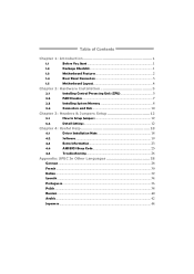
... Memory 8 2.4 Connectors and Slots 10 Chapter 3: Headers & Jumpers Setup 12 3.1 How to Setup Jumpers 12 3.2 Detail Settings 12 Chapter 4: Useful Help 18 4.1 Driver Installation Note 18 4.2 Software 19 4.3 Extra Information 23 4.4 AMI BIOS Beep Code 25 4.5 Troubleshooting 26 Appendix: SPEC In Other Languages 28 German...28 French ...30 Italian......
... Memory 8 2.4 Connectors and Slots 10 Chapter 3: Headers & Jumpers Setup 12 3.1 How to Setup Jumpers 12 3.2 Detail Settings 12 Chapter 4: Useful Help 18 4.1 Driver Installation Note 18 4.2 Software 19 4.3 Extra Information 23 4.4 AMI BIOS Beep Code 25 4.5 Troubleshooting 26 Appendix: SPEC In Other Languages 28 German...28 French ...30 Italian......
Setup Manual
Page 3
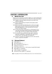
...air and water. 1.2 PACKAGE CHECKLIST HDD Cable X 1 Serial ATA Cable X 1 Rear I/O Panel for choosing our product. CHAPTER 1: INTRODUCTION G41-M7 1.1 BEFORE YOU START Thank you take the motherboard out from anti-static bag, ground yourself properly by touching any unfastened small parts inside ) FDD...132; Do not leave any safely grounded appliance, or use grounded wrist strap to area or your motherboard version. 1 Before you start installing the motherboard, please make sure you follow the instructions below: „ Prepare a dry and stable working environment with sufficient lighting. ...
...air and water. 1.2 PACKAGE CHECKLIST HDD Cable X 1 Serial ATA Cable X 1 Rear I/O Panel for choosing our product. CHAPTER 1: INTRODUCTION G41-M7 1.1 BEFORE YOU START Thank you take the motherboard out from anti-static bag, ground yourself properly by touching any unfastened small parts inside ) FDD...132; Do not leave any safely grounded appliance, or use grounded wrist strap to area or your motherboard version. 1 Before you start installing the motherboard, please make sure you follow the instructions below: „ Prepare a dry and stable working environment with sufficient lighting. ...
Setup Manual
Page 7
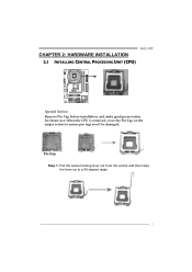
Pin-Cap Step 1: Pull the socket locking lever out from the socket and then raise the lever up to ensure pin legs won't be damaged. G41-M7 CHAPTER 2: HARDWARE INSTALLATION 2.1 INSTALLING CENTRAL PROCESSING UNIT (CPU) Special Notice: Remove Pin Cap before installation, and make good preservation for future use. When the CPU is removed, cover the Pin Cap on the empty socket to a 90-degree angle. 5
Pin-Cap Step 1: Pull the socket locking lever out from the socket and then raise the lever up to ensure pin legs won't be damaged. G41-M7 CHAPTER 2: HARDWARE INSTALLATION 2.1 INSTALLING CENTRAL PROCESSING UNIT (CPU) Special Notice: Remove Pin Cap before installation, and make good preservation for future use. When the CPU is removed, cover the Pin Cap on the empty socket to a 90-degree angle. 5
Setup Manual
Page 8
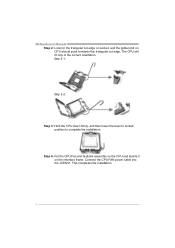
Motherboard Manual Step 2: Look for the triangular cut edge. This completes the installation. 6 Connect the CPU FAN power cable into the JCFAN1. The CPU will fit only in the correct orientation. Step 2-1: Step 2-2: Step 3: Hold the CPU down firmly, and then lower the lever to locked position to complete the installation. Step 4: Put the CPU Fan and heatsink assembly on the CPU and buckle it on CPU should point forwards this triangular cut edge on socket, and the golden dot on the retention frame.
Motherboard Manual Step 2: Look for the triangular cut edge. This completes the installation. 6 Connect the CPU FAN power cable into the JCFAN1. The CPU will fit only in the correct orientation. Step 2-1: Step 2-2: Step 3: Hold the CPU down firmly, and then lower the lever to locked position to complete the installation. Step 4: Put the CPU Fan and heatsink assembly on the CPU and buckle it on CPU should point forwards this triangular cut edge on socket, and the golden dot on the retention frame.
Setup Manual
Page 10
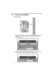
Unlock a DIMM slot by pressing the retaining clips outward. Align a DIMM on the slot such that the notch on the DIMM matches the break on the Slot. 2. DDR2 module 1. Insert the DIMM vertically and firmly into the slot until the retaining chip snap back in place and the DIMM is properly seated. 8 DD R2_A1 DD R2_B1 Motherboard Manual 2.3 INSTALLING SYSTEM MEMORY A.
Unlock a DIMM slot by pressing the retaining clips outward. Align a DIMM on the slot such that the notch on the DIMM matches the break on the Slot. 2. DDR2 module 1. Insert the DIMM vertically and firmly into the slot until the retaining chip snap back in place and the DIMM is properly seated. 8 DD R2_A1 DD R2_B1 Motherboard Manual 2.3 INSTALLING SYSTEM MEMORY A.
Setup Manual
Page 11
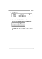
C. Dual Channel Status DDR2_A1 DDR2_B1 Disabled O X Disabled X O Enabled O O (O means memory installed; X, not installed.) The DRAM bus width of the same density in pairs, shown in the table. Memory Capacity DIMM Socket Location DDR2_A1 DDR2_B1 DDR2 Module 256MB/512MB/1GB/2GB 256MB/512MB/1GB/2GB G41-M7 Total Memory Size Max is 4GB. B. Dual Channel Memory Installation Please refer to the following requirements to activate Dual Channel function: Install memory module of the memory module must be the same(x8 or x16) 9
C. Dual Channel Status DDR2_A1 DDR2_B1 Disabled O X Disabled X O Enabled O O (O means memory installed; X, not installed.) The DRAM bus width of the same density in pairs, shown in the table. Memory Capacity DIMM Socket Location DDR2_A1 DDR2_B1 DDR2 Module 256MB/512MB/1GB/2GB 256MB/512MB/1GB/2GB G41-M7 Total Memory Size Max is 4GB. B. Dual Channel Memory Installation Please refer to the following requirements to activate Dual Channel function: Install memory module of the memory module must be the same(x8 or x16) 9
Setup Manual
Page 20
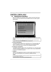
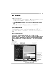
...CD The setup guide will need Acrobat Reader to locate and execute the file SETUP.EXE under your optical drive. Driver Installation To install the driver, please click on the Software icon. C. Click on the Manual icon to browse for your motherboard and operating... 4: USEFUL HELP 4.1 DRIVER INSTALLATION NOTE After you installed your operating system, please insert the Fully Setup Driver CD into your optical drive and install the driver for your system, click on each device driver to launch the installation program. B. Software Installation To install the software, please click on...
...CD The setup guide will need Acrobat Reader to locate and execute the file SETUP.EXE under your optical drive. Driver Installation To install the driver, please click on the Software icon. C. Click on the Manual icon to browse for your motherboard and operating... 4: USEFUL HELP 4.1 DRIVER INSTALLATION NOTE After you installed your operating system, please insert the Fully Setup Driver CD into your optical drive and install the driver for your system, click on each device driver to launch the installation program. B. Software Installation To install the software, please click on...
Setup Manual
Page 21
... drive. Provide the name of the memor y module manufacturer. Save these information to our tech-support department to help you . 4.2 SOFTWARE G41-M7 Installing Software 1. eHot-Line (Optional) eHot-Line is useful for analyzing the problem you may not be collected in forma tion to contact with...and the model no. Provide the e-ma il addr ess that helps you would appear if the Autorun function has been enabled. 2. Select Software Installation, and then click on the desktop. This bl ock will see the software icon "eHOT Line" / "BIOS Update" appears on the respective ...
... drive. Provide the name of the memor y module manufacturer. Save these information to our tech-support department to help you . 4.2 SOFTWARE G41-M7 Installing Software 1. eHot-Line (Optional) eHot-Line is useful for analyzing the problem you may not be collected in forma tion to contact with...and the model no. Provide the e-ma il addr ess that helps you would appear if the Autorun function has been enabled. 2. Select Software Installation, and then click on the desktop. This bl ock will see the software icon "eHOT Line" / "BIOS Update" appears on the respective ...
Setup Manual
Page 28
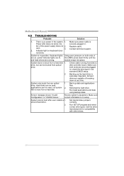
... is Power LED does not shine; System does not boot from an optical 1. drive. Reformat the hard drive. System cannot boot after user installs a 1. second hard drive. 2. Set master/slave jumpers correctly. Replace cable. Indicator light on , power indicator lights are securely plugged in setup...System only boots from a hard disk 1. fails to disk controller board. Run SETUP program and select correct drive types. Re-install applications and data using backup disks. All hard disks are capable of breaking down firmly until the and hard drives are on ...
... is Power LED does not shine; System does not boot from an optical 1. drive. Reformat the hard drive. System cannot boot after user installs a 1. second hard drive. 2. Set master/slave jumpers correctly. Replace cable. Indicator light on , power indicator lights are securely plugged in setup...System only boots from a hard disk 1. fails to disk controller board. Run SETUP program and select correct drive types. Re-install applications and data using backup disks. All hard disks are capable of breaking down firmly until the and hard drives are on ...

Bios Setup
Page 5
... re PATA (Default) / Behind PAT A Legacy IDE Channels T his item appears only when " AT A/IDE Configuration" is a sub-menu fo r each IDE/SAT A device. G41D-M7 BIOS M anual Floppy A Select the type of floppy disk drive installed in / None IDE Configuration T he BIOS will automatically detect the presence of detailed options.
... re PATA (Default) / Behind PAT A Legacy IDE Channels T his item appears only when " AT A/IDE Configuration" is a sub-menu fo r each IDE/SAT A device. G41D-M7 BIOS M anual Floppy A Select the type of floppy disk drive installed in / None IDE Configuration T he BIOS will automatically detect the presence of detailed options.

Bios Setup
Page 6
... vxx .xx (C)Copyright 1985-200x, American Me gatrends, Inc. Options: Auto (Default) / Disabled Block (Multi-Sector Transfer) Enable or disable multi-sector trans fer. G41D-M7 BIOS M anual SATA1/2/3/4 Dev ice; S elect Screen S elect Item +- Options: Auto (Default) / SWDMA0 ~ 2 / MWDMA0 ~ 2 / UDMA0 ~ 5 5 Options: Auto (Default) / Disabled PIO Mode Select the PIO mode...
... vxx .xx (C)Copyright 1985-200x, American Me gatrends, Inc. Options: Auto (Default) / Disabled Block (Multi-Sector Transfer) Enable or disable multi-sector trans fer. G41D-M7 BIOS M anual SATA1/2/3/4 Dev ice; S elect Screen S elect Item +- Options: Auto (Default) / SWDMA0 ~ 2 / MWDMA0 ~ 2 / UDMA0 ~ 5 5 Options: Auto (Default) / Disabled PIO Mode Select the PIO mode...

Bios Setup
Page 10
G41D-M7 BIOS M anual SuperIO Configuration Advanced BIOS S ETUP UTILITY Confi gure...nable or D isable Flopp y Cont roller S elect Screen S elect Item +- Onboard Floppy Controller Select enabled if your system has a floppy disk controller (FDC) installed on AC Powe r Loss [ Enabled] [ 3F8/IRQ4] [ Normal] [ 2F8/IRQ3] [ Normal] [ 378] [ Normal] [ IRQ7] [ Disabled] ... 3F8/IRQ4 (Default) / 3E8/IRQ4 / 2E8/IRQ3 / Disabled Serial Port1 M ode T his item allows you installed another FDC or the system uses no floppy drive, select disabled in this field. If you to determine how the serial ...
G41D-M7 BIOS M anual SuperIO Configuration Advanced BIOS S ETUP UTILITY Confi gure...nable or D isable Flopp y Cont roller S elect Screen S elect Item +- Onboard Floppy Controller Select enabled if your system has a floppy disk controller (FDC) installed on AC Powe r Loss [ Enabled] [ 3F8/IRQ4] [ Normal] [ 2F8/IRQ3] [ Normal] [ 378] [ Normal] [ IRQ7] [ Disabled] ... 3F8/IRQ4 (Default) / 3E8/IRQ4 / 2E8/IRQ3 / Disabled Serial Port1 M ode T his item allows you installed another FDC or the system uses no floppy drive, select disabled in this field. If you to determine how the serial ...


