Setup Manual
Page 3
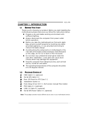
CHAPTER 1: INTRODUCTION G31-M4 1.1 BEFORE YOU START Thank you take the motherboard out from dangerous area, such as heat source, humid air and water. „ The operating temperatures of the board unless necessary. Before you start installing the motherboard, please make sure you follow the ...computer from anti-static bag, ground yourself properly by touching any unfastened small parts inside the case after installation. Hold the board on motherboard or the rear side of the computer should be 0 to 45 degrees Celsius. 1.2 PACKAGE CHECKLIST HDD Cable X 1 (optional) Serial...
CHAPTER 1: INTRODUCTION G31-M4 1.1 BEFORE YOU START Thank you take the motherboard out from dangerous area, such as heat source, humid air and water. „ The operating temperatures of the board unless necessary. Before you start installing the motherboard, please make sure you follow the ...computer from anti-static bag, ground yourself properly by touching any unfastened small parts inside the case after installation. Hold the board on motherboard or the rear side of the computer should be 0 to 45 degrees Celsius. 1.2 PACKAGE CHECKLIST HDD Cable X 1 (optional) Serial...
Setup Manual
Page 4
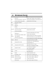
Motherboard Manual 1.3 MOTHERBOARD FEATURES SPEC Socket 478 Supports Hyper-Threading / Execute Disable Bit / CPU Intel Pentium4 /Celeron D / Celeron 3xx Enhanced Intel SpeedStep® / Intel Architecture-64 / processors (Maximum Watt: 95W) Extended Memory 64 Technology FSB Support 800 / 533 MHz Chipset Intel G31 Intel ICH7 ITE 8721 Super I/O Provides the most commonly used legacy Environment...
Motherboard Manual 1.3 MOTHERBOARD FEATURES SPEC Socket 478 Supports Hyper-Threading / Execute Disable Bit / CPU Intel Pentium4 /Celeron D / Celeron 3xx Enhanced Intel SpeedStep® / Intel Architecture-64 / processors (Maximum Watt: 95W) Extended Memory 64 Technology FSB Support 800 / 533 MHz Chipset Intel G31 Intel ICH7 ITE 8721 Super I/O Provides the most commonly used legacy Environment...
Setup Manual
Page 6
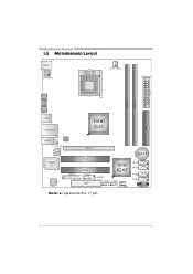
BAT1 SATA4 SATA3 SATA2 SATA1 PANEL1 4 Motherboard Manual 1.5 MOTHERBOARD LAYOUT KB MS1 ATXP W R2 Socket 478 CPU_FAN1 ATXPWR1 DDR 2_A1 DDR 2_B1 VGA1 ID E1 USB 2 RJ 45US B1 Intel G31 AUDIO1 BIOS F_AUDIOF1 LAN PEX16_1 Super I/O Codec JPRNT1 PCI1 PCI2 JCOM1 FDD1 Intel ICH7 JCMOS1 F_USB1 F_USB2 SYS_FAN1 Note: ■ represents the 1st pin.
BAT1 SATA4 SATA3 SATA2 SATA1 PANEL1 4 Motherboard Manual 1.5 MOTHERBOARD LAYOUT KB MS1 ATXP W R2 Socket 478 CPU_FAN1 ATXPWR1 DDR 2_A1 DDR 2_B1 VGA1 ID E1 USB 2 RJ 45US B1 Intel G31 AUDIO1 BIOS F_AUDIOF1 LAN PEX16_1 Super I/O Codec JPRNT1 PCI1 PCI2 JCOM1 FDD1 Intel ICH7 JCMOS1 F_USB1 F_USB2 SYS_FAN1 Note: ■ represents the 1st pin.
Setup Manual
Page 11
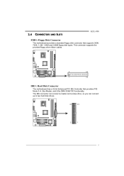
This connector supports the provided floppy drive ribbon cables. 2 34 1 33 IDE1: Hard Disk Connector The motherboard has a 32-bit Enhanced PCI IDE Controller that supports 360K, 720K, 1.2M, 1.44M and 2.88M floppy disk types. 2.4 CONNECTORS AND SLOTS G31-M4 FDD1: Floppy Disk Connector The motherboard provides a standard floppy disk connector that provides PIO Mode 0~4, Bus Master, and Ultra DMA 33/66/100 functionality. The IDE connector can connect a master and a slave drive, so you can connect up to two hard disk drives. 40 39 2 1 9
This connector supports the provided floppy drive ribbon cables. 2 34 1 33 IDE1: Hard Disk Connector The motherboard has a 32-bit Enhanced PCI IDE Controller that supports 360K, 720K, 1.2M, 1.44M and 2.88M floppy disk types. 2.4 CONNECTORS AND SLOTS G31-M4 FDD1: Floppy Disk Connector The motherboard provides a standard floppy disk connector that provides PIO Mode 0~4, Bus Master, and Ultra DMA 33/66/100 functionality. The IDE connector can connect a master and a slave drive, so you can connect up to two hard disk drives. 40 39 2 1 9
Setup Manual
Page 13
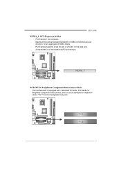
Maximum theoretical realized bandwidth of 4GB/s simultaneously per direction, for expansion cards. PEX16_1 PCI1/PCI2: Peripheral Component Interconnect Slots This motherboard is designated as 32 bits. PCI1 PCI2 11 G31-M4 PEX16_1: PCI-Express x16 Slot - PCI-Express 1.0a compliant. - PCI stands for Peripheral Component Interconnect, and it is a bus standard for an aggregate of 2.5Gb/s on the data pins. - 2X bandwidth over the traditional PCI architecture. This PCI slot is equipped with 2 standard PCI slots. PCI-Express supports a raw bit-rate of 8GB/s totally. -
Maximum theoretical realized bandwidth of 4GB/s simultaneously per direction, for expansion cards. PEX16_1 PCI1/PCI2: Peripheral Component Interconnect Slots This motherboard is designated as 32 bits. PCI1 PCI2 11 G31-M4 PEX16_1: PCI-Express x16 Slot - PCI-Express 1.0a compliant. - PCI stands for Peripheral Component Interconnect, and it is a bus standard for an aggregate of 2.5Gb/s on the data pins. - 2X bandwidth over the traditional PCI architecture. This PCI slot is equipped with 2 standard PCI slots. PCI-Express supports a raw bit-rate of 8GB/s totally. -
Setup Manual
Page 15
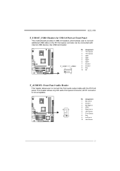
... 2 Ground 3 Mic Right in 4 GPIO 5 Right line in 6 Jack Sense 7 Front Sense 8 Key 9 Left line in 10 Jack Sense 13 G31-M4 F_USB1/F_USB2: Headers for USB 2.0 Ports at Front Panel This motherboard provides 2 USB 2.0 headers, which allows user to connect the front audio output cable with internal USB devices, like USB card...
... 2 Ground 3 Mic Right in 4 GPIO 5 Right line in 6 Jack Sense 7 Front Sense 8 Key 9 Left line in 10 Jack Sense 13 G31-M4 F_USB1/F_USB2: Headers for USB 2.0 Ports at Front Panel This motherboard provides 2 USB 2.0 headers, which allows user to connect the front audio output cable with internal USB devices, like USB card...
Setup Manual
Page 17
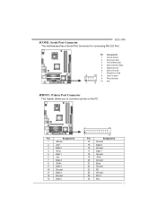
... 22 23 24 25 26 25 Assignment Ground Data 6 Ground Data 7 Ground -ACK Ground Busy Ground PE Ground SCLT Key 15 JCOM1: Serial Port Connector G31-M4 The motherboard has a Serial Port Connector for connecting RS-232 Port.
... 22 23 24 25 26 25 Assignment Ground Data 6 Ground Data 7 Ground -ACK Ground Busy Ground PE Ground SCLT Key 15 JCOM1: Serial Port Connector G31-M4 The motherboard has a Serial Port Connector for connecting RS-232 Port.
Setup Manual
Page 21
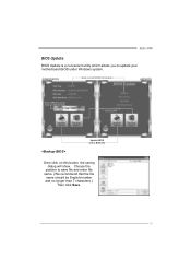
G31-M4 BIOS Update BIOS Update is a convenient utility which allows you to save file and enter file name. (We recommend that the file name should be English/number and no longer than 7 characters.) Then click Save. 19 Choose the position to update your motherboard BIOS under Windows system. AWARD BIOS Show current BIOS information AMI BIOS Clear CMOS function (Only for AWARD BIOS) Save current BIOS to a .bin file Update BIOS with a BIOS file Once click on this button, the saving dialog will show.
G31-M4 BIOS Update BIOS Update is a convenient utility which allows you to save file and enter file name. (We recommend that the file name should be English/number and no longer than 7 characters.) Then click Save. 19 Choose the position to update your motherboard BIOS under Windows system. AWARD BIOS Show current BIOS information AMI BIOS Clear CMOS function (Only for AWARD BIOS) Save current BIOS to a .bin file Update BIOS with a BIOS file Once click on this button, the saving dialog will show.
Setup Manual
Page 23
CPU fan is over heated, the motherboard will shutdown automatically to relief the CPU protection function. 1. After confirmed, please follow steps below to avoid a damage of the CPU, and the system may ... double check: 1. CPU fan speed is placed evenly with the CPU speed. Plug in the power cord and boot up the system. Wait for seconds. 3. G31-M4 4.3 EXTRA INFORMATION CPU Overheated If the system shutdown automatically after power on the system again. 21 Or you can: 1. Power on system for seconds. 2. The...
CPU fan is over heated, the motherboard will shutdown automatically to relief the CPU protection function. 1. After confirmed, please follow steps below to avoid a damage of the CPU, and the system may ... double check: 1. CPU fan speed is placed evenly with the CPU speed. Plug in the power cord and boot up the system. Wait for seconds. 3. G31-M4 4.3 EXTRA INFORMATION CPU Overheated If the system shutdown automatically after power on the system again. 21 Or you can: 1. Power on system for seconds. 2. The...
Setup Manual
Page 25
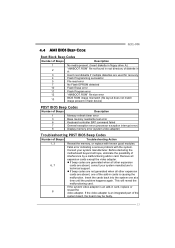
...system video adapter is an add-in cards is an integrated part of interference by a malfunctioning add-in card. 4.4 AMI BIOS BEEP CODE G31-M4 Boot Block Beep Codes Number of Beeps Description 1 No media present. (Insert diskette in floppy drive A:) 2 "AMIBOOT.ROM" file not ...the cards back into the system one of Beeps Troubleshooting Action 1, 3 Reseat the memory, or replace with the system. Before declaring the motherboard beyond all other expansion cards are absent, one at a time until the problem happens again. Consult your system manufacturer's technical support. z ...
...system video adapter is an add-in cards is an integrated part of interference by a malfunctioning add-in card. 4.4 AMI BIOS BEEP CODE G31-M4 Boot Block Beep Codes Number of Beeps Description 1 No media present. (Insert diskette in floppy drive A:) 2 "AMIBOOT.ROM" file not ...the cards back into the system one of Beeps Troubleshooting Action 1, 3 Reseat the memory, or replace with the system. Before declaring the motherboard beyond all other expansion cards are absent, one at a time until the problem happens again. Consult your system manufacturer's technical support. z ...
Setup Manual
Page 44
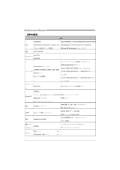
Motherboard Manual JAPANESE 仕様 Socket 478 Hyper-Threading / Execute Disable Bit / Enhanced Intel CPU Intel Pentium4 /Celeron D / Celeron 3xx SpeedStep® / Intel Architecture-64 / Extended 95W) Memory 64 Technology FSB 800 / 533 MHz Intel G31 Intel ICH7 DDR2 DDR2 DIMM x 2 各DIMMは 256MB / 512MB / 1GB / 2GB DDR2 4GB DDR2 533/667...
Motherboard Manual JAPANESE 仕様 Socket 478 Hyper-Threading / Execute Disable Bit / Enhanced Intel CPU Intel Pentium4 /Celeron D / Celeron 3xx SpeedStep® / Intel Architecture-64 / Extended 95W) Memory 64 Technology FSB 800 / 533 MHz Intel G31 Intel ICH7 DDR2 DDR2 DIMM x 2 各DIMMは 256MB / 512MB / 1GB / 2GB DDR2 4GB DDR2 533/667...
Bios Setup
Page 2
... to the hard disk drives and video monitors can do without accessing programs from a disk. The rest of the EPA Green PC specification. G31-M4 BIOS Manual BIOS Setup Introduction The purpose of CMOS RAM is supplied by a battery so that it retains the Setup information when the power is... to describe the settings in the AMI BIOS Setup program on this motherboard. The power of this AMI BIOS. It provides ASL code for power management and device configuration capabilities as defined in BIOS. BIOS activates at...
... to the hard disk drives and video monitors can do without accessing programs from a disk. The rest of the EPA Green PC specification. G31-M4 BIOS Manual BIOS Setup Introduction The purpose of CMOS RAM is supplied by a battery so that it retains the Setup information when the power is... to describe the settings in the AMI BIOS Setup program on this motherboard. The power of this AMI BIOS. It provides ASL code for power management and device configuration capabilities as defined in BIOS. BIOS activates at...
Bios Setup
Page 3
...Self-Test (POST) to select item and change the settings. The actual BIOS information and settings on board may be changed without notice. G31-M4 BIOS Manual PCI Bus Support This AMI BIOS also supports Version 2.3 of this manual. We will see General Help description at the bottom ...right corner, and you will not be responsible for that may be slightly different from this manual is providing a brief description of the motherboard. Navigation Keys for any settings, please load the default settings to be caused by wrong-settings. 2 DRAM Support DDR2 SDRAM (Double Data ...
...Self-Test (POST) to select item and change the settings. The actual BIOS information and settings on board may be changed without notice. G31-M4 BIOS Manual PCI Bus Support This AMI BIOS also supports Version 2.3 of this manual. We will see General Help description at the bottom ...right corner, and you will not be responsible for that may be slightly different from this manual is providing a brief description of the motherboard. Navigation Keys for any settings, please load the default settings to be caused by wrong-settings. 2 DRAM Support DDR2 SDRAM (Double Data ...
Bios Setup
Page 13
...server is a server-specific feature. Options: Disabled (Default) / Enabled HPET Memory Address Options: Options: FED00000h (Default) / FED01000h / FED02000h / FED03000h 12 G31-M4 BIOS Manual ACPI APIC support This item is used to set APIC ACPI SCI by IRQ. To run in the Root System Description Table (RSDT...: Enabled (Default) / Disabled AMI OEMB table Set this value to allow the ACPI BIOS to add a pointer to enable or disable the motherboard's APIC (Advanced Programmable Interrupt Controller). Options: Disabled (Default) / Enabled APIC ACPI SCI IRQ This item is used to an OEMB table in...
...server is a server-specific feature. Options: Disabled (Default) / Enabled HPET Memory Address Options: Options: FED00000h (Default) / FED01000h / FED02000h / FED03000h 12 G31-M4 BIOS Manual ACPI APIC support This item is used to set APIC ACPI SCI by IRQ. To run in the Root System Description Table (RSDT...: Enabled (Default) / Disabled AMI OEMB table Set this value to allow the ACPI BIOS to add a pointer to enable or disable the motherboard's APIC (Advanced Programmable Interrupt Controller). Options: Disabled (Default) / Enabled APIC ACPI SCI IRQ This item is used to an OEMB table in...
Bios Setup
Page 14
... from PCI card returns the system to enable if applicable. Options: Disabled (Default) / Enabled Resume On RTC Alarm When "Enabled", you control the wake on motherboard to Full ON state. Options: Disabled (Default) / Enabled RTC Alarm Date (Days) You can choose the system boot up . For this function to specify. 13...
... from PCI card returns the system to enable if applicable. Options: Disabled (Default) / Enabled Resume On RTC Alarm When "Enabled", you control the wake on motherboard to Full ON state. Options: Disabled (Default) / Enabled RTC Alarm Date (Days) You can choose the system boot up . For this function to specify. 13...

