

User Guide
Page 1
Z170-AR Motherboard
Z170-AR Motherboard

User Guide
Page 3
Contents Safety information...v About this guide...v Package contents...vii Z170-AR specifications summary vii Chapter 1: Product Introduction 1.1 Before you proceed 1-1 1.2 Motherboard overview 1-1 1.3 Central Processing Unit (CPU 1-4 1.4 System memory 1-8 1.5 Expansion slots 1-16 1.6 Jumpers...1-19 1.7 Connectors 1-21 1.8 Onboard LEDs 1-34 1.9 Onboard buttons and switches 1-36 1.10 Software support 1-...
Contents Safety information...v About this guide...v Package contents...vii Z170-AR specifications summary vii Chapter 1: Product Introduction 1.1 Before you proceed 1-1 1.2 Motherboard overview 1-1 1.3 Central Processing Unit (CPU 1-4 1.4 System memory 1-8 1.5 Expansion slots 1-16 1.6 Jumpers...1-19 1.7 Connectors 1-21 1.8 Onboard LEDs 1-34 1.9 Onboard buttons and switches 1-36 1.10 Software support 1-...

User Guide
Page 5
... • Seek professional assistance before using the product, ensure all power cables are not damaged. It includes descriptions of the motherboard and the new technology it by yourself. Contact a qualified service technician or your retailer. If you are using, contact your ...the features of the switches, jumpers, and connectors on a stable surface. • If you need when installing and configuring the motherboard. Safety information Electrical safety • To prevent electrical shock hazard, disconnect the power cable from the electrical outlet before relocating the system...
... • Seek professional assistance before using the product, ensure all power cables are not damaged. It includes descriptions of the motherboard and the new technology it by yourself. Contact a qualified service technician or your retailer. If you are using, contact your ...the features of the switches, jumpers, and connectors on a stable surface. • If you need when installing and configuring the motherboard. Safety information Electrical safety • To prevent electrical shock hazard, disconnect the power cable from the electrical outlet before relocating the system...
User Guide
Page 7
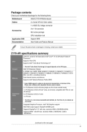
... (max. Intel® HD Graphics support Multi-VGA output support: DisplayPort/HDMI ports Supports DisplayPort 1.2* with max. Z170-AR specifications summary LGA1151 socket for 6th Generation Intel® Core™ i7/ i5/ i3/Pentium®/Celeron® ...Boost Technology 2.0 support depends on the next page) vii Package contents Check your motherboard package for the following items: Motherboard ASUS Z170-AR Motherboard Cables 2 x Serial ATA 6.0 Gb/s cables 1 x ASUS SLI bridge connector Accessories 2-in-1 Q-connector M.2 screw package CPU installation tool Application...
... (max. Intel® HD Graphics support Multi-VGA output support: DisplayPort/HDMI ports Supports DisplayPort 1.2* with max. Z170-AR specifications summary LGA1151 socket for 6th Generation Intel® Core™ i7/ i5/ i3/Pentium®/Celeron® ...Boost Technology 2.0 support depends on the next page) vii Package contents Check your motherboard package for the following items: Motherboard ASUS Z170-AR Motherboard Cables 2 x Serial ATA 6.0 Gb/s cables 1 x ASUS SLI bridge connector Accessories 2-in-1 Q-connector M.2 screw package CPU installation tool Application...

User Guide
Page 13
... with the component. • Before you install or remove any component, ensure that the motherboard fits. ASUS Z170-AR Series 1-1 Chapter 1: Product Introduction Product Introduction 1 1.1 Before you proceed Take note of the following precautions before you install motherboard components or change any motherboard settings. • Unplug the power cord from the power supply. Do not overtighten...
... with the component. • Before you install or remove any component, ensure that the motherboard fits. ASUS Z170-AR Series 1-1 Chapter 1: Product Introduction Product Introduction 1 1.1 Before you proceed Take note of the following precautions before you install motherboard components or change any motherboard settings. • Unplug the power cord from the power supply. Do not overtighten...

User Guide
Page 14
Place this side towards the rear of the chassis 1.2.3 Motherboard layout 1-2 Chapter 1: Product Introduction
Place this side towards the rear of the chassis 1.2.3 Motherboard layout 1-2 Chapter 1: Product Introduction

User Guide
Page 16
... if the PnP cap is on the LGA1151 socket. • Ensure that all power cables are not bent. ASUS will process Return Merchandise Authorization (RMA) requests only if the motherboard comes with a surface mount LGA1151 socket designed for LGA1151 socket only. DO NOT install a CPU designed for other... with the cap on the LGA1150 socket. • The product warranty does not cover damage to the PnP cap/socket contacts/motherboard components. ASUS will shoulder the cost of the PnP cap. 1-4 Chapter 1: Product Introduction Ensure that the PnP cap is missing, or if you install...
... if the PnP cap is on the LGA1151 socket. • Ensure that all power cables are not bent. ASUS will process Return Merchandise Authorization (RMA) requests only if the motherboard comes with a surface mount LGA1151 socket designed for LGA1151 socket only. DO NOT install a CPU designed for other... with the cap on the LGA1150 socket. • The product warranty does not cover damage to the PnP cap/socket contacts/motherboard components. ASUS will shoulder the cost of the PnP cap. 1-4 Chapter 1: Product Introduction Ensure that the PnP cap is missing, or if you install...

User Guide
Page 20
DO NOT install a DDR, DDR2, or DDR3 memory module to the DDR4 slot. 1-8 Chapter 1: Product Introduction To uninstall the CPU heatsink and fan assembly 1.4 System memory 1.4.1 Overview The motherboard comes with four Double Data Rate 4 (DDR4) Dual Inline Memory Modules (DIMM) slots. A DDR4 module is notched differently from a DDR, DDR2, or DDR3 module.
DO NOT install a DDR, DDR2, or DDR3 memory module to the DDR4 slot. 1-8 Chapter 1: Product Introduction To uninstall the CPU heatsink and fan assembly 1.4 System memory 1.4.1 Overview The motherboard comes with four Double Data Rate 4 (DDR4) Dual Inline Memory Modules (DIMM) slots. A DDR4 module is notched differently from a DDR, DDR2, or DDR3 module.
User Guide
Page 21
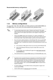
... the higher-sized channel is dependent on the motherboard, the actual usable memory for the OS can refer to the recommended memory population below. • You may operate at : www.asus.com for single-channel operation. • Always install DIMMs with the same CAS latency. ASUS Z170-AR Series 1-9 Recommended memory configurations 1.4.2 Memory configurations You...
... the higher-sized channel is dependent on the motherboard, the actual usable memory for the OS can refer to the recommended memory population below. • You may operate at : www.asus.com for single-channel operation. • Always install DIMMs with the same CAS latency. ASUS Z170-AR Series 1-9 Recommended memory configurations 1.4.2 Memory configurations You...

User Guide
Page 22
... • 1.35V • 1-10 Chapter 1: Product Introduction Size CORSAIR CMD16GX4M4B3400C16 16GB(4GB*4) ver. 4.23 SS/DS Chip Brand Chip NO. Size SS/ Chip Chip NO. Z170-AR Motherboard Qualified Vendors Lists (QVL) DDR4 3400 (O.C.) MHz capability Vendors Part No.
... • 1.35V • 1-10 Chapter 1: Product Introduction Size CORSAIR CMD16GX4M4B3400C16 16GB(4GB*4) ver. 4.23 SS/DS Chip Brand Chip NO. Size SS/ Chip Chip NO. Z170-AR Motherboard Qualified Vendors Lists (QVL) DDR4 3400 (O.C.) MHz capability Vendors Part No.

User Guide
Page 28
Unplug the power cord before adding or removing expansion cards. Remove the system unit cover (if your motherboard is completely seated on the slot. 5. Failure to do so may need to install expansion cards. Keep the screw for the card. 2. Replace ...the system cover. 1-16 Chapter 1: Product Introduction Secure the card to the chassis with the screw you physical injury and damage motherboard components. 1.5.1 Installing an expansion card To install an expansion card: 1. Remove the bracket opposite the slot that you may cause you removed earlier. 6. ...
Unplug the power cord before adding or removing expansion cards. Remove the system unit cover (if your motherboard is completely seated on the slot. 5. Failure to do so may need to install expansion cards. Keep the screw for the card. 2. Replace ...the system cover. 1-16 Chapter 1: Product Introduction Secure the card to the chassis with the screw you physical injury and damage motherboard components. 1.5.1 Installing an expansion card To install an expansion card: 1. Remove the bracket opposite the slot that you may cause you removed earlier. 6. ...
User Guide
Page 29
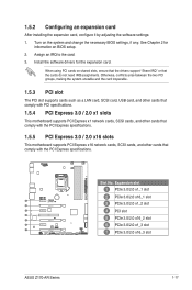
...slot PCIe 3.0/2.0 x1_1 slot PCIe 3.0/2.0 x16_1 slot PCIe 3.0/2.0 x1_2 slot PCI slot PCIe 3.0/2.0 x16_2 slot PCIe 3.0/2.0 x1_3 slot PCIe 3.0/2.0 x16_3 slot ASUS Z170-AR Series 1-17 Assign an IRQ to the card. 3. Otherwise, conflicts arise between the two PCI groups, making the system unstable and the card ...LAN card, SCSI card, USB card, and other cards that comply with PCI specifications. 1.5.4 PCI Express 3.0 / 2.0 x1 slots This motherboard supports PCI Express x1 network cards, SCSI cards, and other cards that comply with the PCI Express specifications. When using PCI cards on ...
...slot PCIe 3.0/2.0 x1_1 slot PCIe 3.0/2.0 x16_1 slot PCIe 3.0/2.0 x1_2 slot PCI slot PCIe 3.0/2.0 x16_2 slot PCIe 3.0/2.0 x1_3 slot PCIe 3.0/2.0 x16_3 slot ASUS Z170-AR Series 1-17 Assign an IRQ to the card. 3. Otherwise, conflicts arise between the two PCI groups, making the system unstable and the card ...LAN card, SCSI card, USB card, and other cards that comply with PCI specifications. 1.5.4 PCI Express 3.0 / 2.0 x1 slots This motherboard supports PCI Express x1 network cards, SCSI cards, and other cards that comply with the PCI Express specifications. When using PCI cards on ...

User Guide
Page 30
... recommend that you provide sufficient power when running CrossFireX™ or SLI™ mode. • Connect a chassis fan to the motherboard connector labeled CHA_FAN1-4 when using multiple graphics cards for this motherboard PCIE x16_1 PCIE x16_2 PCIE x16_3 PCIE x1_1 PCIE x1_2 PCIE x1_3 SMBUS Controller Intel SATA Controller Intel LAN Intel...
... recommend that you provide sufficient power when running CrossFireX™ or SLI™ mode. • Connect a chassis fan to the motherboard connector labeled CHA_FAN1-4 when using multiple graphics cards for this motherboard PCIE x16_1 PCIE x16_2 PCIE x16_3 PCIE x1_1 PCIE x1_2 PCIE x1_3 SMBUS Controller Intel SATA Controller Intel LAN Intel...

User Guide
Page 37
... 4-pin CHA_FAN1-4) Connect the fan cables to the fan connectors on water cooling device. • The CPU_FAN connector and CHA_FAN connectors support the ASUS FAN Xpert 3 feature. • The CPU fan connector detects the type of the connector. • DO NOT forget to connect the fan...• W_PUMP function support depends on the motherboard, ensuring that the black wire of each cable matches the ground pin of CPU fan installed and automatically switches the control modes. Do not place jumper caps on the fan connectors! ASUS Z170-AR Series 1-25 Insufficient air flow inside the ...
... 4-pin CHA_FAN1-4) Connect the fan cables to the fan connectors on water cooling device. • The CPU_FAN connector and CHA_FAN connectors support the ASUS FAN Xpert 3 feature. • The CPU fan connector detects the type of the connector. • DO NOT forget to connect the fan...• W_PUMP function support depends on the motherboard, ensuring that the black wire of each cable matches the ground pin of CPU fan installed and automatically switches the control modes. Do not place jumper caps on the fan connectors! ASUS Z170-AR Series 1-25 Insufficient air flow inside the ...
User Guide
Page 39
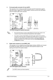
..., set to a slot opening at the back of the motherboard's high-definition audio capability. • If you want to connect a high-definition front panel audio module to this connector, set the item to [HD Audio]. See section 2.6.8 Onboard Devices Configuration for details. 6. ASUS Z170-AR Series 1-27 The S/PDIF module is set the Front...
..., set to a slot opening at the back of the motherboard's high-definition audio capability. • If you want to connect a high-definition front panel audio module to this connector, set the item to [HD Audio]. See section 2.6.8 Onboard Devices Configuration for details. 6. ASUS Z170-AR Series 1-27 The S/PDIF module is set the Front...

User Guide
Page 40
...; This socket supports M Key and type 2242/2260/2280/22110 storage devices. • The M.2 (NGFF) SSD module is for details. 8. Change this connector on the motherboard. 7. Refer to this item before installing M.2 SATA devices. 1-28 Chapter 1: Product Introduction Ensure that your chassis comes with the extra button cable that supports the...
...; This socket supports M Key and type 2242/2260/2280/22110 storage devices. • The M.2 (NGFF) SSD module is for details. 8. Change this connector on the motherboard. 7. Refer to this item before installing M.2 SATA devices. 1-28 Chapter 1: Product Introduction Ensure that your chassis comes with the extra button cable that supports the...
User Guide
Page 41
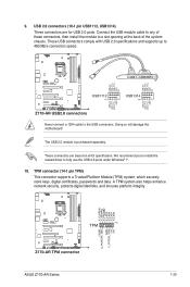
... supports up to the USB connectors. A TPM system also helps enhance network security, protects digital identities, and ensures platform integrity. Doing so will damage the motherboard! The USB 2.0 module is purchased separately. We recommend you to install the related driver to a slot opening at the back of these connectors, then install... securely store keys, digital certificates, passwords and data. 9. These connectors are for USB 2.0 ports. Connect the USB module cable to any of the system chassis. ASUS Z170-AR Series 1-29
... supports up to the USB connectors. A TPM system also helps enhance network security, protects digital identities, and ensures platform integrity. Doing so will damage the motherboard! The USB 2.0 module is purchased separately. We recommend you to install the related driver to a slot opening at the back of these connectors, then install... securely store keys, digital certificates, passwords and data. 9. These connectors are for USB 2.0 ports. Connect the USB module cable to any of the system chassis. ASUS Z170-AR Series 1-29

User Guide
Page 44
.... T_Sensor connector (2-pin T_SENSOR) This connector is for the add-on Thunderbolt I /O card that allows you to connect up to monitor the temperature of your motherboard's critical components and connected devices. Thunderbolt header (5-pin TB_HEADER) This connector is purchased separately. 1-32 Chapter 1: Product Introduction 13.
.... T_Sensor connector (2-pin T_SENSOR) This connector is for the add-on Thunderbolt I /O card that allows you to connect up to monitor the temperature of your motherboard's critical components and connected devices. Thunderbolt header (5-pin TB_HEADER) This connector is purchased separately. 1-32 Chapter 1: Product Introduction 13.

User Guide
Page 46
Standby Power LED The motherboard comes with a standby power LED that lights up until the problem is solved. 1-34 Chapter 1: Product Introduction This is a reminder that the system is found, ... critical component's LED stays lit up to indicate that you should shut down the system and unplug the power cable before removing or plugging any motherboard components. POST State LEDs The POST State LEDs provide the status of the onboard LED. 2. 1.8 Onboard LEDs 1. The illustration below shows the location of these...
Standby Power LED The motherboard comes with a standby power LED that lights up until the problem is solved. 1-34 Chapter 1: Product Introduction This is a reminder that the system is found, ... critical component's LED stays lit up to indicate that you should shut down the system and unplug the power cable before removing or plugging any motherboard components. POST State LEDs The POST State LEDs provide the status of the onboard LED. 2. 1.8 Onboard LEDs 1. The illustration below shows the location of these...

User Guide
Page 48
... • We recommend that are not compatible with ones recommended in the Memory QVL (Qualified Vendors Lists) in this user manual or at www.asus.com. • If you turn off the system and reinstall the DIMM before using the MemOK! 1.9 Onboard buttons and switches Onboard buttons and ...compatibility tuning and reboot for overclockers and gamers who continually change settings to boot and load the BIOS default settings. Replace the DIMMs with the motherboard may cause system boot failure. It takes about 5-10 seconds. • If your system fails to boot up when the DIMM is ...
... • We recommend that are not compatible with ones recommended in the Memory QVL (Qualified Vendors Lists) in this user manual or at www.asus.com. • If you turn off the system and reinstall the DIMM before using the MemOK! 1.9 Onboard buttons and switches Onboard buttons and ...compatibility tuning and reboot for overclockers and gamers who continually change settings to boot and load the BIOS default settings. Replace the DIMMs with the motherboard may cause system boot failure. It takes about 5-10 seconds. • If your system fails to boot up when the DIMM is ...


