
User Guide
Page 1
Motherboard X99-WS/ IPMI
Motherboard X99-WS/ IPMI

User Guide
Page 3
...X99-WS/IPMI specifications summary ix Package contents...xiii Installation tools and components xiv Chapter 1: Product Introduction 1.1 Special features 1-1 1.1.1 Product highlights 1-1 1.1.2 Other special features 1-2 1.2 Motherboard overview 1-3 1.2.1 Before you proceed 1-3 1.2.2 Motherboard...18 1.2.8 Onboard LEDs 1-22 1.2.9 Internal connectors 1-30 Chapter 2: Basic installation 2.1 Building your PC system 2-1 2.1.1 Motherboard installation 2-1 2.1.2 CPU installation 2-3 2.1.3 CPU heatsink and fan assembly installation 2-4 2.1.4 DIMM installation 2-6 2.1.5 ATX ...
...X99-WS/IPMI specifications summary ix Package contents...xiii Installation tools and components xiv Chapter 1: Product Introduction 1.1 Special features 1-1 1.1.1 Product highlights 1-1 1.1.2 Other special features 1-2 1.2 Motherboard overview 1-3 1.2.1 Before you proceed 1-3 1.2.2 Motherboard...18 1.2.8 Onboard LEDs 1-22 1.2.9 Internal connectors 1-30 Chapter 2: Basic installation 2.1 Building your PC system 2-1 2.1.1 Motherboard installation 2-1 2.1.2 CPU installation 2-3 2.1.3 CPU heatsink and fan assembly installation 2-4 2.1.4 DIMM installation 2-6 2.1.5 ATX ...

User Guide
Page 6
... circuit. • Ensure that came with the product, contact a qualified service technician or your retailer. Operation safety • Before installing the motherboard and adding devices on a stable surface. • If you are using, contact your dealer immediately. • To avoid short circuits, keep... to the correct voltage in your retailer. If you add a device. • Before connecting or removing signal cables from the motherboard, ensure that the power cables for the devices are unplugged before the signal cables are connected. Safety information Electrical safety •...
... circuit. • Ensure that came with the product, contact a qualified service technician or your retailer. Operation safety • Before installing the motherboard and adding devices on a stable surface. • If you are using, contact your dealer immediately. • To avoid short circuits, keep... to the correct voltage in your retailer. If you add a device. • Before connecting or removing signal cables from the motherboard, ensure that the power cables for the devices are unplugged before the signal cables are connected. Safety information Electrical safety •...

User Guide
Page 7
...This chapter lists the hardware setup procedures that you need when installing and configuring the motherboard. ASUS website The ASUS website (www.asus.com) provides updated information on the motherboard. 2. Chapter 6: Multi GPU support This chapter describes how to change system settings through... RAID configurations. 6. Optional documentation Your product package may include optional documentation, such as warranty flyers, that comes with the motherboard package and the software. 5. These documents are also provided. 4. Chapter 3: BIOS setup This chapter tells how to install...
...This chapter lists the hardware setup procedures that you need when installing and configuring the motherboard. ASUS website The ASUS website (www.asus.com) provides updated information on the motherboard. 2. Chapter 6: Multi GPU support This chapter describes how to change system settings through... RAID configurations. 6. Optional documentation Your product package may include optional documentation, such as warranty flyers, that comes with the motherboard package and the software. 5. These documents are also provided. 4. Chapter 3: BIOS setup This chapter tells how to install...
User Guide
Page 13
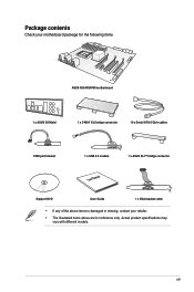
xiii Actual product specifications may vary with different models. Package contents Check your motherboard package for the following items ASUS X99-WS/IPMI motherboard 1 x ASUS Q-Shield 1 x 3-WAY SLI bridge connector 10 x Serial ATA 6 Gb/s cables COM port bracket 1 x USB 2.0 module 1 x ASUS SLI™ bridge connector User Manual Support DVD User Guide 1 x VGA bracket cable • If any of the above items is damaged or missing, contact your retailer. • The illustrated items above are for reference only.
xiii Actual product specifications may vary with different models. Package contents Check your motherboard package for the following items ASUS X99-WS/IPMI motherboard 1 x ASUS Q-Shield 1 x 3-WAY SLI bridge connector 10 x Serial ATA 6 Gb/s cables COM port bracket 1 x USB 2.0 module 1 x ASUS SLI™ bridge connector User Manual Support DVD User Guide 1 x VGA bracket cable • If any of the above items is damaged or missing, contact your retailer. • The illustrated items above are for reference only.

User Guide
Page 14
Installation tools and components Intel® LGA2011-v3 CPU Intel® LGA2011-v3 compatible CPU Fan PC chassis SATA hard disk drive Philips (cross) screwdriver Power supply unit 1 bag of screws DIMM SATA optical disc drive (optional) Graphics card The tools and components in the table above are not included in the motherboard package. xiv
Installation tools and components Intel® LGA2011-v3 CPU Intel® LGA2011-v3 compatible CPU Fan PC chassis SATA hard disk drive Philips (cross) screwdriver Power supply unit 1 bag of screws DIMM SATA optical disc drive (optional) Graphics card The tools and components in the table above are not included in the motherboard package. xiv

User Guide
Page 15
...® 3.0 PCI Express® 3.0 (PCIe 3.0) is the PCI Express bus standard that is a single chipset that features data transfer rates of PCIe 2.0. Chapter 1 ASUS X99-WS/IPMI 1-1 Quad-Channel DDR4 2133 MHz Support The motherboard supports the quad-channel DDR4 memory that supports the LGA2011-v3 socket for Intel® Core™ i7 processors This...
...® 3.0 PCI Express® 3.0 (PCIe 3.0) is the PCI Express bus standard that is a single chipset that features data transfer rates of PCIe 2.0. Chapter 1 ASUS X99-WS/IPMI 1-1 Quad-Channel DDR4 2133 MHz Support The motherboard supports the quad-channel DDR4 memory that supports the LGA2011-v3 socket for Intel® Core™ i7 processors This...

User Guide
Page 16
... UltraPC II delivers a superior surround sound experience through augmenting low and high frequencies of incredible surround sound. Chapter 1 1-2 Chapter 1: Product introduction Complete USB 3.0 integration This motherboard offers you the strategic USB 3.0 accessibility for both the front and rear panels, allowing you to experience the convenience of the latest plug and play...
... UltraPC II delivers a superior surround sound experience through augmenting low and high frequencies of incredible surround sound. Chapter 1 1-2 Chapter 1: Product introduction Complete USB 3.0 integration This motherboard offers you the strategic USB 3.0 accessibility for both the front and rear panels, allowing you to experience the convenience of the latest plug and play...

User Guide
Page 17
... install or remove any component, ensure that the ATX power supply is switched off or the power cord is detached from the power supply. Chapter 1 ASUS X99-WS/IPMI 1-3 1.2 Motherboard overview 1.2.1 Before you proceed Take note of the following precautions before touching any component. • Before handling components, use a grounded wrist strap or touch a safely... or a metal object, such as the power supply case, to avoid damaging them due to static electricity. • Hold components by the edges to the motherboard, peripherals, or components.
... install or remove any component, ensure that the ATX power supply is switched off or the power cord is detached from the power supply. Chapter 1 ASUS X99-WS/IPMI 1-3 1.2 Motherboard overview 1.2.1 Before you proceed Take note of the following precautions before touching any component. • Before handling components, use a grounded wrist strap or touch a safely... or a metal object, such as the power supply case, to avoid damaging them due to static electricity. • Hold components by the edges to the motherboard, peripherals, or components.

User Guide
Page 18
1.2.2 Motherboard layout Chapter 1 Refer to 1.2.9 Internal connectors and 2.4.1 Rear I/O connection for more information about rear panel connectors and internal connectors. 1-4 Chapter 1: Product introduction
1.2.2 Motherboard layout Chapter 1 Refer to 1.2.9 Internal connectors and 2.4.1 Rear I/O connection for more information about rear panel connectors and internal connectors. 1-4 Chapter 1: Product introduction

User Guide
Page 20
... the CPU. • Upon purchase of the motherboard, ensure that the PnP cap is on the LGA2011-v3 socket. • The product warranty does not cover damage to the PnP cap/socket contacts/motherboard components. ASUS will process Return Merchandise Authorization (RMA) requests only... if the motherboard comes with a surface mount LGA2011-v3 socket designed for Intel® Core™ i7 processors. ...
... the CPU. • Upon purchase of the motherboard, ensure that the PnP cap is on the LGA2011-v3 socket. • The product warranty does not cover damage to the PnP cap/socket contacts/motherboard components. ASUS will process Return Merchandise Authorization (RMA) requests only... if the motherboard comes with a surface mount LGA2011-v3 socket designed for Intel® Core™ i7 processors. ...

User Guide
Page 21
Recommended memory configurations Chapter 1 ASUS X99-WS/IPMI 1-7 A DDR4 module is notched differently from a DDR, DDR2, or DDR3 module. DO NOT install a DDR, DDR2, or DDR3 memory module to the DDR4 slot. 1.2.4 System memory The motherboard comes with eight DDR 4 (Double Data Rate 4) Quad Inline Memory Modules (DIMM) slots.
Recommended memory configurations Chapter 1 ASUS X99-WS/IPMI 1-7 A DDR4 module is notched differently from a DDR, DDR2, or DDR3 module. DO NOT install a DDR, DDR2, or DDR3 memory module to the DDR4 slot. 1.2.4 System memory The motherboard comes with eight DDR 4 (Double Data Rate 4) Quad Inline Memory Modules (DIMM) slots.

User Guide
Page 22
...the same version or data code (D/C) from the same vendor. Check with the vendor to get the correct memory modules. • ASUS exclusively provides hyper DIMM support function. • Hyper DIMM support is subject to install 4 GB or more details, refer to support...section 3.5 Ai Tweaker menu for single-channel operation. • According to Intel® CPU spec, DIMM voltage below 1.65 V is dependent on the motherboard. settings in Channel A, Channel B, Channel C, and Channel D. Any excess memory from a memory module. Chapter 1 1-8 Chapter 1: Product introduction Load the ...
...the same version or data code (D/C) from the same vendor. Check with the vendor to get the correct memory modules. • ASUS exclusively provides hyper DIMM support function. • Hyper DIMM support is subject to install 4 GB or more details, refer to support...section 3.5 Ai Tweaker menu for single-channel operation. • According to Intel® CPU spec, DIMM voltage below 1.65 V is dependent on the motherboard. settings in Channel A, Channel B, Channel C, and Channel D. Any excess memory from a memory module. Chapter 1 1-8 Chapter 1: Product introduction Load the ...

User Guide
Page 23
1.2.5 Expansion slots Unplug the power cord before adding or removing expansion cards. ASUS X99-WS/IPMI 1-9 Chapter 1 Slot No. 1 2 3 4 5 40-LANE PCIe 3.0/2.0 x16_1 slot PCIe 3.0/2.0 x16_2 slot PCIe 3.0/2.0 x16_3 slot PCIe 3.0/2.0 x16_4 slot PCIe 3.0/2.0 x16_5 slot Slot Description 28-LANE PCIe 3.0/2.0 x16_1 slot PCIe 3.0/2.0 x16_2 slot PCIe 3.0/2.0 x16_3 slot PCIe 3.0/2.0 x16_4 slot* PCIe 3.0/2.0 x16_5 slot *This slot may cause you physical injury and damage motherboard components. Failure to do so may not work if a 28-LANE CPU is installed.
1.2.5 Expansion slots Unplug the power cord before adding or removing expansion cards. ASUS X99-WS/IPMI 1-9 Chapter 1 Slot No. 1 2 3 4 5 40-LANE PCIe 3.0/2.0 x16_1 slot PCIe 3.0/2.0 x16_2 slot PCIe 3.0/2.0 x16_3 slot PCIe 3.0/2.0 x16_4 slot PCIe 3.0/2.0 x16_5 slot Slot Description 28-LANE PCIe 3.0/2.0 x16_1 slot PCIe 3.0/2.0 x16_2 slot PCIe 3.0/2.0 x16_3 slot PCIe 3.0/2.0 x16_4 slot* PCIe 3.0/2.0 x16_5 slot *This slot may cause you physical injury and damage motherboard components. Failure to do so may not work if a 28-LANE CPU is installed.

User Guide
Page 24
... N/A N/A x8 x8 N/A x4 • We recommend that you provide sufficient power when running CrossFireX™ or SLI™ mode. • Connect a chassis fan to the motherboard connector labeled REAR_FAN1 or FRNT_ FAN1-3 when using multiple graphics cards for better thermal environment. Chapter 1 1-10 Chapter 1: Product introduction
... N/A N/A x8 x8 N/A x4 • We recommend that you provide sufficient power when running CrossFireX™ or SLI™ mode. • Connect a chassis fan to the motherboard connector labeled REAR_FAN1 or FRNT_ FAN1-3 when using multiple graphics cards for better thermal environment. Chapter 1 1-10 Chapter 1: Product introduction

User Guide
Page 25
PCIe x16_5 shared - - - - - - SMBUS Controller - - Intel® SATA Controller 2 shared - - - - - - - shared Intel® EHCI 1 - - - - - shared - shared - - - - - Chapter 1 ASUS X99-WS/IPMI 1-11 IRQ assignments for this motherboard A B C D E F G H PCIe x16_1 shared - - - - - - - shared - - - - - Intel® SATA Controller 1 - Intel® xHCI - - - - - - - shared - - - - - AST2400 VGA shared - - - - - - - shared - - shared - - - - Intel® EHCI 2 - - HD Audio - - - - - ...
PCIe x16_5 shared - - - - - - SMBUS Controller - - Intel® SATA Controller 2 shared - - - - - - - shared Intel® EHCI 1 - - - - - shared - shared - - - - - Chapter 1 ASUS X99-WS/IPMI 1-11 IRQ assignments for this motherboard A B C D E F G H PCIe x16_1 shared - - - - - - - shared - - - - - Intel® SATA Controller 1 - Intel® xHCI - - - - - - - shared - - - - - AST2400 VGA shared - - - - - - - shared - - shared - - - - Intel® EHCI 2 - - HD Audio - - - - - ...

User Guide
Page 26
... overclockers and gamers who continually change settings to reboot the system. Reset button Press the reset button to enhance system performance. 1. Power-on button The motherboard comes with a power-on a bare or open-case system. Chapter 1 1-12 Chapter 1: Product introduction 1.2.6 Onboard buttons and switches Onboard buttons and switches allow you should...
... overclockers and gamers who continually change settings to reboot the system. Reset button Press the reset button to enhance system performance. 1. Power-on button The motherboard comes with a power-on a bare or open-case system. Chapter 1 1-12 Chapter 1: Product introduction 1.2.6 Onboard buttons and switches Onboard buttons and switches allow you should...

User Guide
Page 27
button lights continuously. The blinking speed of failsafe settings. ASUS X99-WS/IPMI 1-13 Chapter 1 Press and hold the MemOK! button until the DIAG_DRAM LED...reminding you download and update to boot up when the DIMM is tested. Replace the DIMMs with the motherboard may cause system boot failure, and the DIAG_DRAM LED near the MemOK! button Installing DIMMs that you... It takes about 5-10 seconds. • If your system fails to the latest BIOS version from www.asus.com after using the MemOK! If the installed DIMMs still fail to boot and load the BIOS default settings...
button lights continuously. The blinking speed of failsafe settings. ASUS X99-WS/IPMI 1-13 Chapter 1 Press and hold the MemOK! button until the DIAG_DRAM LED...reminding you download and update to boot up when the DIMM is tested. Replace the DIMMs with the motherboard may cause system boot failure, and the DIAG_DRAM LED near the MemOK! button Installing DIMMs that you... It takes about 5-10 seconds. • If your system fails to the latest BIOS version from www.asus.com after using the MemOK! If the installed DIMMs still fail to boot and load the BIOS default settings...

User Guide
Page 45
ASUS X99-WS/IPMI 1-31 Chapter 1 • These connectors are set , refer to the manual bundled in the ... drives, you intend to create a Serial ATA RAID set using these connectors, set the SATA Mode item in the motherboard support DVD. • The SATAEXPRESS_1 connector can create a RAID 0, 1, 5, and 10 configuration with the Intel® Rapid... Storage Technology through the onboard Intel® X99 chipset. If you can support one SATA Express device or two SATA devices. • Due to [RAID Mode]. Refer to...
ASUS X99-WS/IPMI 1-31 Chapter 1 • These connectors are set , refer to the manual bundled in the ... drives, you intend to create a Serial ATA RAID set using these connectors, set the SATA Mode item in the motherboard support DVD. • The SATAEXPRESS_1 connector can create a RAID 0, 1, 5, and 10 configuration with the Intel® Rapid... Storage Technology through the onboard Intel® X99 chipset. If you can support one SATA Express device or two SATA devices. • Due to [RAID Mode]. Refer to...

User Guide
Page 46
... Serial ATA hard disk drives that allows up to 3 Gbps of this user guide. 5. For more information on the SATA RAID solutions supported on this motherboard, refer to create a RAID 0, RAID 1, RAID 5, or a RAID 10 configuration. 4.
... Serial ATA hard disk drives that allows up to 3 Gbps of this user guide. 5. For more information on the SATA RAID solutions supported on this motherboard, refer to create a RAID 0, RAID 1, RAID 5, or a RAID 10 configuration. 4.

